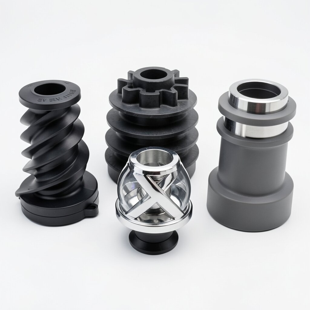
SK Type Helical Static Mixer
Helical Twist Static Mixer
Single-twist helical element for the most viscous process fluids — heavy oils, polymer melts, animal fats, and sludge-dewatering polymers.
Product Overview
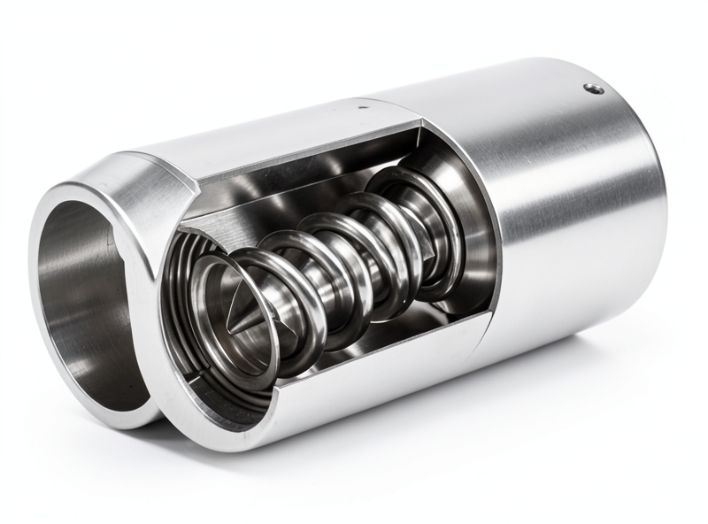
When the process fluid behaves more like cold honey than like water, the SK type helical static mixer is the model that does the work. Inside the housing, a series of flat metal blades — twisted 180° or 270° from inlet face to outlet face — sit one behind the other. Each successive element is rotated 90° to its neighbor, so the flow that has been twisted clockwise by one element is immediately counter-twisted by the next. The net effect is not droplet breakup (that is the domain of the SV and SX); it is the controlled folding and reorientation of viscous streamlines until the composition profile is uniform across the pipe cross-section.
The headline specification of the SK is its 1,000,000 cP viscosity ceiling — three to four orders of magnitude beyond the SV, SX, and SL models. That is what makes the SK the only static mixer in the ywmixing catalog that can be specified for the most punishing heavy-industrial services: Bunker C fuel oil and bitumen blending, polymer melt homogenization, animal-fat and hydrogenated-oil processing, and the activation of high-molecular-weight flocculants in sludge dewatering. None of these applications would work in a plate or bar mixer, because the fluids would simply refuse to flow through the narrow channels.
The SK also has the lowest clogging risk of any model in our line. The twisted-blade geometry has no closed channels and no small orifices; anything that will pass through the pipe bore will pass through the mixer. This makes the SK the default choice for slurries with up to 30% solids by volume, fibrous media, and other "dirty" services. The trade-off is coarser dispersion: SK delivers ≤10 μm droplets, which is fine for blending high-viscosity fluids but is not appropriate when the process needs sub-micron emulsions.
Working Principle
The internal element is a rectangular plate, typically 0.8-2.0 mm thick for stainless steel or 1.5-3.0 mm for carbon steel, twisted along its longitudinal axis. The aspect ratio (width-to-length) of the plate is chosen so that the twisted element just fits inside the housing with a clearance of 1-2 mm to the wall. Standard twist angles are 180° (used in most general-purpose applications) and 270° (used when the additional rotational shear is needed for very viscous media). The element length is usually 1.0-1.5 pipe diameters.
When fluid enters the mixer, the twisted blade forces it into a helical motion. The pitch of the helix is determined by the twist angle and the element length; for a 180° element of length 1.5D, the induced swirl is approximately one full turn over the element. As the fluid exits the first element and enters the second (rotated 90°), the swirl direction is reversed and the flow is forced to reorient. The result is a chaotic, three-dimensional flow pattern in which the original stream tubes are repeatedly stretched, folded, and re-stacked.
The dominant mixing mechanism in the SK is laminar stretching and folding — not turbulent breakup, since most SK applications operate at Re < 1,000 (often Re < 100). This is the regime in which the Kenics static mixer, the parent design of our SK model, has been most thoroughly characterized in the academic literature. The mixing length required to reach σX ≤ 5% is typically 5-8 elements for 180° twist and 4-6 elements for 270° twist. Pressure drop per element is roughly 1.5-3 velocity heads (compared to 5-10 for an SV element), which is why the SK is preferred when the process pump is marginal on head.
Technical Specifications
| Parameter | Value |
|---|---|
| Internal Structure | Single helical twist blade (180° or 270°), adjacent elements rotated 90° with reversed twist direction |
| Dispersion Precision | ≤ 10 μm (coarser than SV/SX; appropriate for viscous blending) |
| Viscosity Range | 1 cP to 1,000,000 cP — highest in the product line |
| Pressure Drop | Moderate; ~1.5-3 velocity heads per element |
| Non-Uniformity Coefficient | σX ≤ 5% with 5-8 elements (180°) or 4-6 elements (270°) |
| Material Options | SS304, SS316L, Carbon Steel, PVC, PP, Hastelloy C-276 |
| Connection Types | Flange (ANSI / DIN / JIS), Threaded (NPT / BSP), Welded, Tri-Clamp |
| Temperature Range | -50°C to +300°C (metallic) / -10°C to +80°C (PVC/PP) |
| Pipe Diameter Range | DN15 to DN500 |
| Flow Rate Range | 0.05 to 800 m³/h (model and pipe-size dependent) |
| Clogging Risk | Lowest of all five models — open geometry, no small channels |
| Internal Structure | Helical twist Corrugated plates Crossed bars Dual-channel helical Single-X bars |
| Dispersion Precision | ≤ 10 μm 1-2 μm 2-5 μm 1-2 mm Medium |
| Max Viscosity (cP) | 1,000,000 100 10,000 1,000,000 10 (or polymer) |
| Pipe Diameter | DN15-DN500 DN15-DN1000 DN25-DN800 DN15-DN200 DN15-DN600 |
| Clogging Risk | Lowest High Moderate Moderate Low |
| Best For | High-viscosity Fine dispersion Mid-range High-viscosity clean Heat transfer |
Frequently Asked Questions
The SK helix mixer is rated for fluids up to 1,000,000 cP kinematic viscosity — the highest of any model in our product line. It is the workhorse for heavy oils, polymer melts, and high-solids slurries.
SK elements are twisted flat blades (180° or 270° over their length) that rotate the flow without splitting it. SX elements use crossed bars that physically split the stream. The SK open geometry means a lower pressure drop at high viscosity but a coarser dispersion (≤10 μm vs SX's 2-5 μm).
Most SK installations use between 5 and 10 elements with each element measuring 1.5D in length, giving a total L/D of 7.5-15. High-viscosity or high-precision applications may use up to 20 elements (L/D ≈ 30).
Yes — the open geometry of the helical element allows CIP fluid to reach every surface. In sanitary service, the housing and elements are specified to Ra ≤ 0.8 μm and use tri-clamp connections for fast disassembly.
Pressure drop is dominated by the frictional loss along the twisted blade surface and the kinetic energy required to redirect the flow 180° per element. The standard formula is ΔP = N × f(Re) × ρv²/2, where f(Re) is the friction factor for the blade geometry, N is the element count, ρ is fluid density, and v is the superficial velocity.
Related Products