
Venturi Injector
Differential-Pressure Chemical Injector for Water Treatment
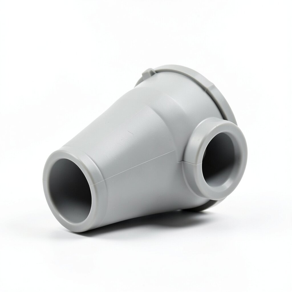
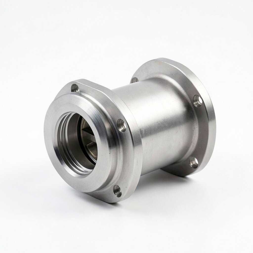
Standard differential-pressure Venturi injector for chemical dosing in water treatment, fertigation, and pH adjustment — no moving parts, motive flow 0.5-50 m³/h, suction lift up to 8 m, PP/PVC/SS316L construction.
Product Overview
The Venturi injector is the simplest and most reliable way to introduce a liquid chemical into a pressurized water stream without using an electrical metering pump. The device exploits the Bernoulli principle: as the main (motive) flow accelerates through a precisely-machined throat, the local static pressure drops below atmospheric, and a side-port allows the chemical from a reservoir at atmospheric pressure to be drawn up through a suction line and into the main stream. No electricity, no moving parts, no calibration drift — the injector is purely a passive fluidic device with a service life of 10+ years and a maintenance interval that is typically limited to a periodic suction-line check-valve cleaning.
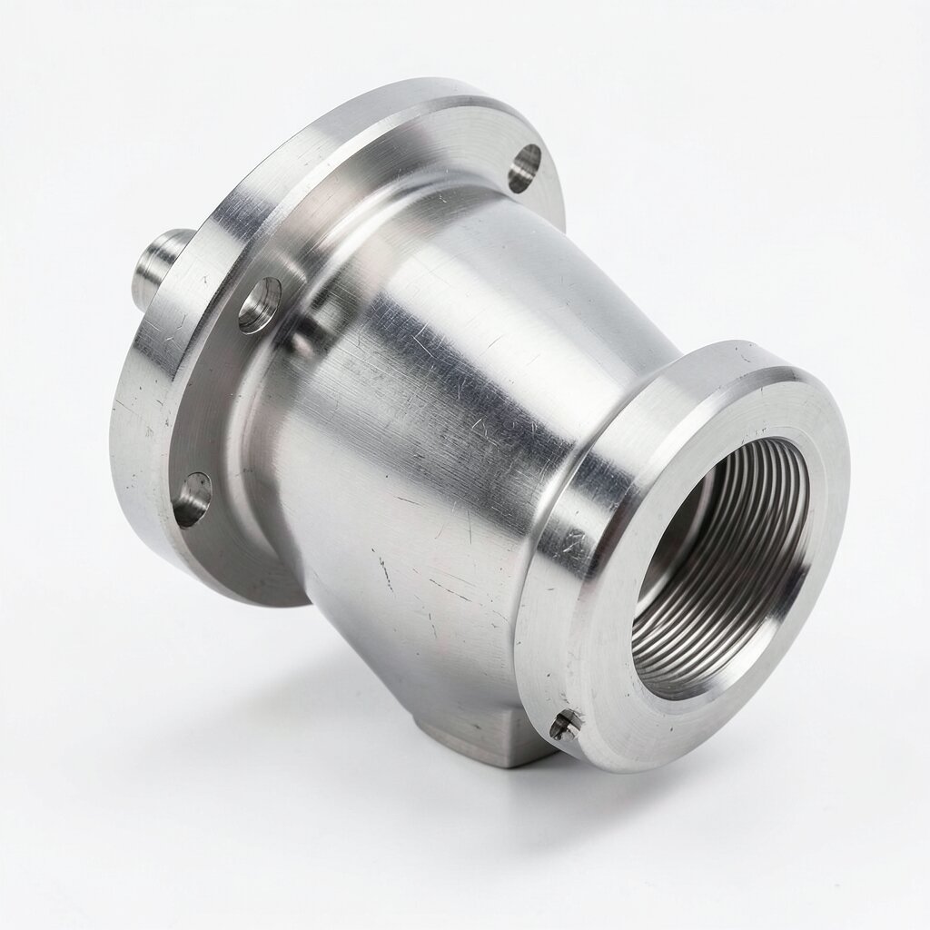
Our standard Venturi injector line is built around four body materials (PP, PVC, PVDF, SS316L) and ten size variants from DN15 to DN150. The PP body is the workhorse for municipal and industrial water treatment — it tolerates the broadest chemical range and is the lowest cost. The SS316L body is specified for hot water, food-grade, and pharmaceutical service, or where the chemical includes organic solvents that would attack PP. PVDF is reserved for high-temperature service (up to 120°C) and aggressive chemistries such as hot concentrated acids.
The performance envelope is set by the throat-to-inlet area ratio β. For our standard designs, β = 0.45-0.55, which is the optimum for the typical water-treatment duty cycle: enough pressure drop to lift the chemical 4-8 m and inject at ratios of 0.1-5% by volume, without excessive motive pressure loss (5-25% of inlet pressure). For low-ratio applications (1:1000 to 1:10000), a high-β variant (β = 0.65-0.75) is offered, which trades injection capacity for a much lower motive pressure drop. For high-ratio applications (1:1 to 1:10), a low-β variant (β = 0.30-0.40) is offered, which lifts more chemical at the cost of a higher motive pressure drop.
The injector is normally supplied as a complete assembly with integral suction port, suction check valve, suction strainer, and (optionally) a flow-regulating needle valve on the suction line. The motive-side connections are flanged (ANSI, DIN, or JIS) by default for DN50 and above, and threaded (NPT or BSP) for DN15 to DN40. Tri-clamp connections are available for sanitary service.
Working Principle
Inside the body, the main (motive) flow enters through the inlet port and converges through a tapered reducer to a precisely-machined throat. The throat diameter is the smallest cross-section in the flow path; by the continuity equation, the velocity at the throat is the highest in the device. By the Bernoulli equation, the local static pressure at the throat is correspondingly the lowest. The side-port (suction port) is connected to the throat through a small bore, so the low-pressure region at the throat is communicated to the suction line.
If the chemical reservoir is at atmospheric pressure and the suction line is primed, the pressure difference between atmosphere and the throat drives the chemical up the suction line and into the throat. The chemical is then accelerated through a diverging diffuser downstream of the throat, where it is mixed into the main flow. By the time the combined stream exits the diffuser, 60-80% of the throat's pressure loss has been recovered as kinetic-to-pressure conversion, so the net motive pressure drop is 5-25% of the inlet pressure — a small parasitic loss compared with the benefit of chemical injection without any electrical power.
The injection flow rate Qinj is given approximately by Qinj = Cd · At · √(2 · ΔP / ρ), where Cd is the discharge coefficient of the suction port (typically 0.6-0.7), At is the throat area, ΔP is the pressure drop from atmosphere to the throat, and ρ is the chemical density. The injection ratio is Qinj / Qmotive; the motive flow Qmotive is set by the upstream pump or pressure, and Qinj is set by the throat geometry and the discharge pressure. A needle valve on the suction line allows Qinj to be throttled independently of the motive conditions, giving a fixed injection ratio at constant motive flow.
Technical Specifications
| Parameter | Value |
|---|---|
| Body Material | PP (standard) / PVC / PVDF / SS316L |
| Throat Material | Same as body; SS316L throat optional in PP body for wear resistance |
| Seal Material | EPDM (standard) / FKM (Viton) / PTFE (high-temp) |
| Nominal Diameter (DN) | 15 / 20 / 25 / 32 / 40 / 50 / 65 / 80 / 100 / 150 |
| Motive Flow Range (DN15) | 0.5-2.5 m³/h |
| Motive Flow Range (DN25) | 1.5-7.0 m³/h |
| Motive Flow Range (DN50) | 6-25 m³/h |
| Motive Flow Range (DN100) | 25-80 m³/h |
| Motive Flow Range (DN150) | 50-200 m³/h |
| Throat-Inlet Area Ratio (β) | 0.45-0.55 (standard) / 0.30-0.40 (high-ratio) / 0.65-0.75 (low-ratio) |
| Motive Pressure Range | 0.5-6 bar (PP/PVC) / 0.5-10 bar (SS316L) / 0.5-16 bar (SS316L heavy-wall) |
| Motive Pressure Drop | 5-25% of inlet pressure (β-dependent) |
| Suction Lift (Max, Theoretical) | 10.3 m (1 atm water column) |
| Suction Lift (Practical) | 6-8 m (PP/PVC) / 4-6 m (SS316L) |
| Injection Ratio Range | 0.1-5% (standard) / 0.01-0.1% (low-β) / 5-50% (high-β) |
| Discharge Coefficient C d (Suction) | 0.60-0.70 (geometry-dependent) |
| Temperature Range (PP) | 0°C to +60°C |
| Temperature Range (PVC) | 0°C to +50°C |
| Temperature Range (PVDF) | -20°C to +120°C |
| Temperature Range (SS316L) | -40°C to +200°C |
| Pressure Recovery (Diffuser) | 60-80% of throat pressure drop recovered |
| End Connections (DN15-DN40) | Threaded NPT 1/2"-1-1/2" or BSP equivalent; Tri-clamp optional |
| End Connections (DN50-DN150) | Flanged ANSI B16.5 Class 150 / DIN PN16 / JIS 10K |
| Suction Port Connection | 1/2" NPT (DN15-DN40) / 3/4" NPT (DN50+) / 1" NPT (DN100+) |
| Suction Check Valve | Spring-loaded PP or SS316L, Cracking pressure 0.05 bar |
| Suction Strainer | 20-mesh PP or SS316L, field-cleanable |
| Net Weight (DN25 PP) | 0.8 kg |
| Net Weight (DN100 SS316L) | 18.5 kg |
Frequently Asked Questions
The pressure drop across the injector is a function of the throat-to-inlet area ratio β and the discharge pressure. For our standard designs, β = 0.45-0.55, and the pressure drop is 5-25% of the inlet (motive) pressure, depending on flow rate and discharge back-pressure. A 2-bar motive pressure with 1.5-bar discharge typically yields a 0.3-0.5 bar drop — enough to lift a chemical 4-6 m and inject it into the main stream.
Limited. The throat diameter is the smallest cross-section and is the most likely site for clogging. Particulate must be < 0.5 mm and fiber content below 50 ppm for reliable service. For slurries, specify the open-throat variant with the optional flushing port — this allows a periodic back-flush with clean water to clear deposits. For heavily-loaded slurries, switch to a diaphragm metering pump with a static mixer downstream.
PP is compatible with most acids (HCl up to 30%, H 2 SO 4 up to 50%, H 3 PO 4 any concentration), bases (NaOH up to 40%, KOH any concentration), salts, and most water-treatment polymers up to 60°C. PP is not suitable for strong oxidizers (concentrated HNO 3 , oleum) or aromatic/chlorinated solvents — for those, specify PVDF or SS316L.
The theoretical maximum suction lift is 10.3 m (1 atm of water column). In practice, the achievable lift is 6-8 m for PP/PVC and 4-6 m for SS316L, because of friction losses in the suction line and the partial-vacuum limit of the available motive pressure drop. Above 8 m, a booster pump or flooded suction (chemical reservoir above the injector) is required.
Three methods are used: (1) a downstream needle valve on the suction line throttles the chemical flow and gives a fixed ratio at constant motive conditions; (2) a metering pump on the suction line overrides the Venturi's natural draw and provides precise, variable-rate injection; (3) a bypass loop on the motive line allows manual modulation of the motive flow, which indirectly modulates the suction flow. Method 1 is the simplest and is used for fixed-ratio applications like chlorination; method 2 is the most flexible and is the standard for plants with multiple setpoints.
Related Products
SS Venturi Injector
All-Stainless Steel Chemical Injector for Hot & Sanitary Service
View Details