
Rotor Flowmeter
Variable-Area Flow Indicator for Chemical Injection Lines
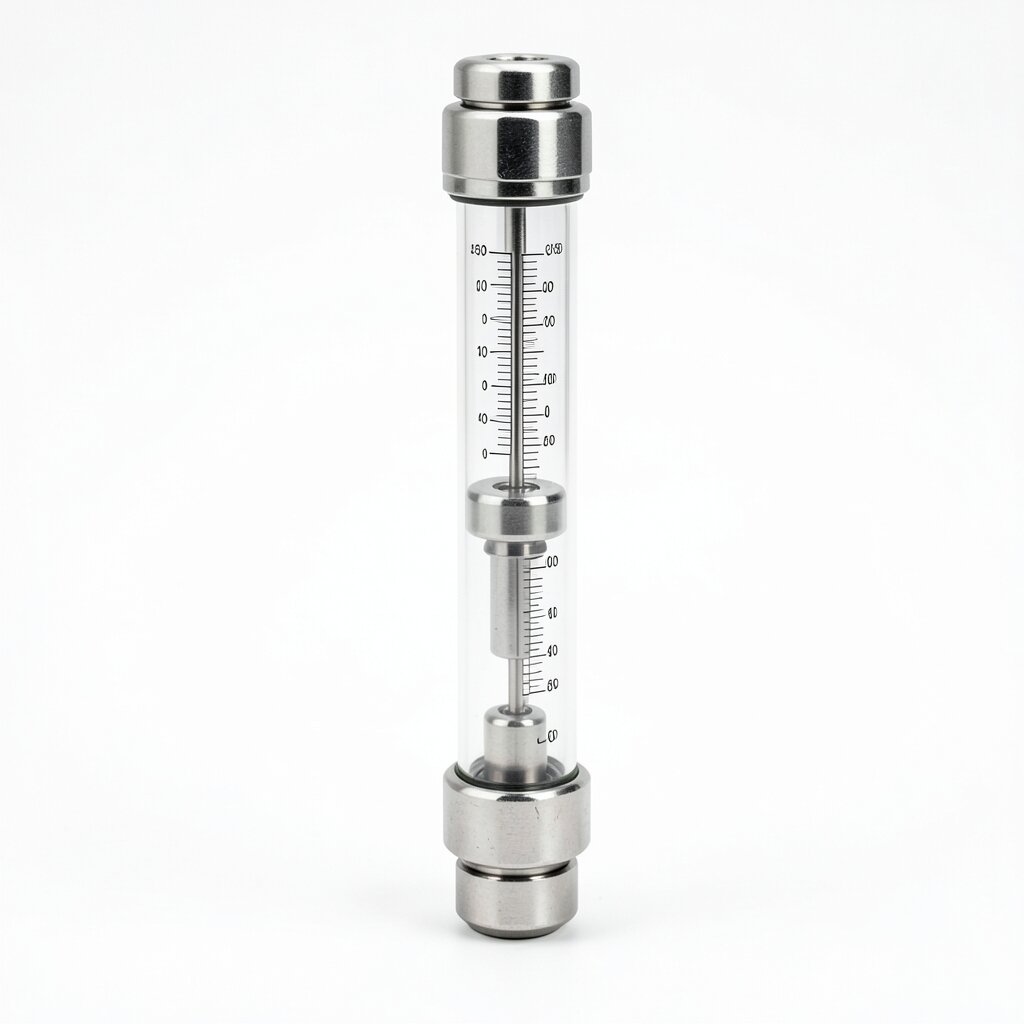
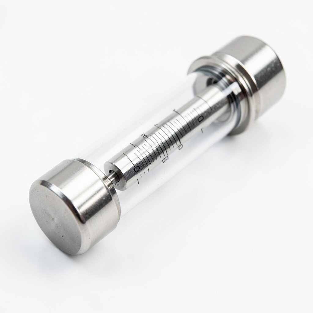
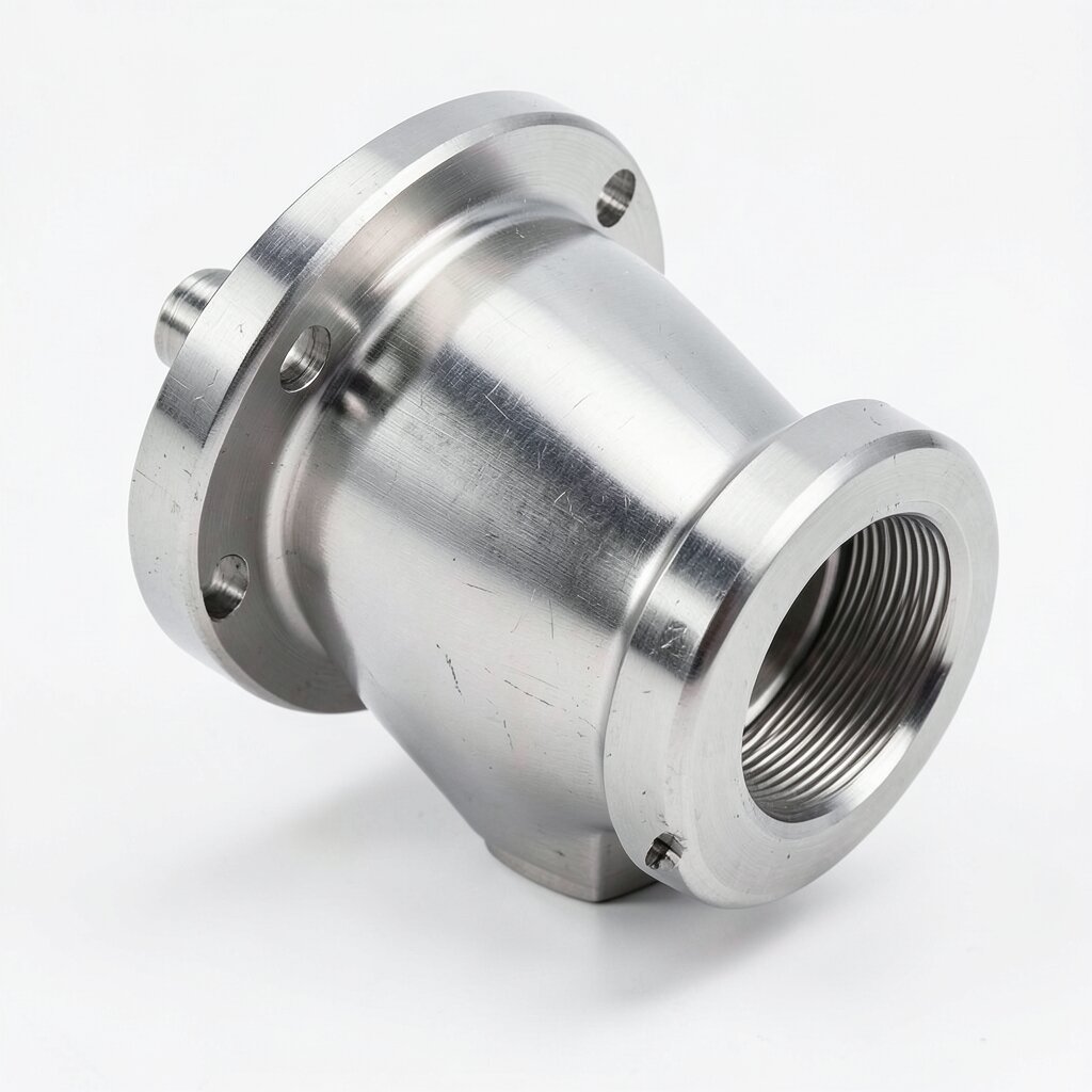
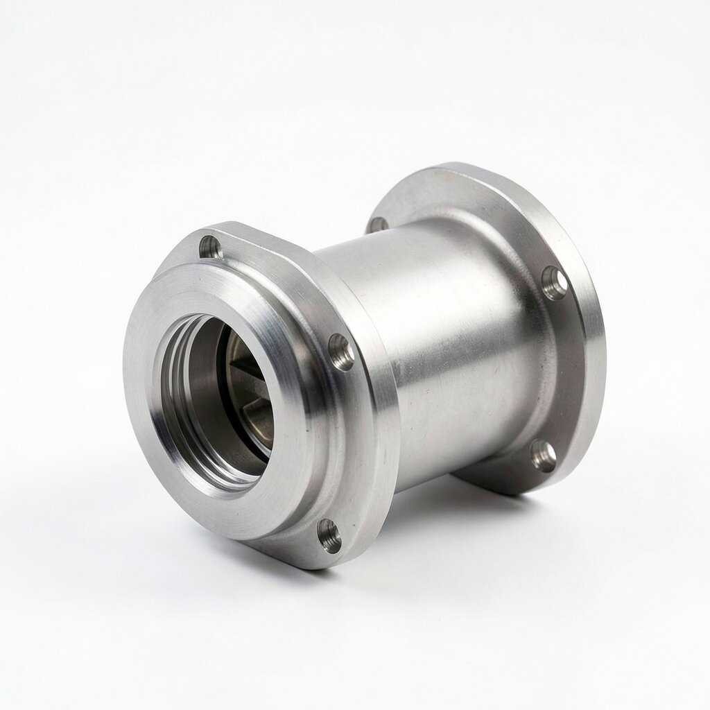
Variable-area rotor flowmeter (rotameter) for chemical-injection-line flow indication — PVDF / SS316L / PSU body, 0.5-150 L/h flow range, ±5% F.S. accuracy, 16-40 bar rated, with optional 4-20 mA transmitter for SCADA integration.
Product Overview
The rotor flowmeter (also called a variable-area flowmeter, rotameter, or float flowmeter) is the simplest, lowest-cost, and most reliable way to get a local visual indication of flow rate on a chemical injection line. The device consists of a precision-tapered tube (typically borosilicate glass for visual indication, or PSU / PVDF for chemical compatibility with no glass) and a calibrated float that is pushed up the tube by the flow. The float's vertical position, read off a graduated scale, gives the flow rate directly. There are no moving parts other than the float itself, no electrical power required, and no electronics to drift or fail in the field.
Our rotor flowmeter line is designed specifically for the chemical injection duty — the low flow rates (0.5-150 L/h), the corrosive chemistry (NaClO, HCl, NaOH, polymers, antiscalants), and the space constraints of a chemical skid. Three body materials cover the bulk of the application space. PVDF body with PVDF float is the workhorse for water-treatment chemicals at ambient temperature; it tolerates HCl up to 30%, NaOH up to 40%, NaClO up to 15%, and most water-treatment polymers, and is rated to 16 bar at 20°C. PSU (polysulfone) body with PSU float is the clear-tube variant for low-pressure service (up to 6 bar) where the operator wants to see the float and visually verify the chemical color. SS316L body with SS316L float and tempered borosilicate glass tube is the high-pressure / high-temperature variant (40 bar, 200°C) for hot-process service and food/pharma.
The rotor flowmeter is a local-indication device. For plants that require remote indication or SCADA integration, an optional 4-20 mA transmitter is available — a magnet-coupled Hall-effect sensor tracks the float position and outputs a proportional 4-20 mA signal that can be tied into the plant DCS. The transmitter is powered from the 24 VDC loop and adds 2% F.S. to the measurement uncertainty.
Working Principle
Inside the tapered tube, the cross-sectional area increases linearly with height (the taper is typically 1:50 to 1:200, depending on the flow range). As the flow enters at the bottom, it pushes the float upward. The float is buoyant in the fluid and experiences three forces: the upward drag force from the flow (which increases with the annular area between the float and the tube), the downward gravitational force (the float's weight minus buoyancy), and (for guided-rod variants) the spring force from the central guide rod.
At any given flow rate, the float reaches an equilibrium position where the drag force exactly balances the weight. Because the annular area between the float and the tube increases with height, the flow velocity at the float's location decreases as the float rises. The drag force is a function of the velocity squared (in turbulent flow) or the velocity (in laminar flow), so the equilibrium is unique. The result is that the float's height is a monotonic function of the flow rate, and the graduated scale on the tube (or on the housing) is calibrated to read the flow rate directly.
The standard rotor flowmeter is calibrated for water at 20°C as a reference. For other fluids, the indicated flow must be corrected by the fluid's density and viscosity. The correction factor K is read from a per-float curve supplied with the flowmeter. K = √(ρwater/ρfluid) for density correction (low-density solvents read high, high-density brines read low), multiplied by an additional viscosity correction for fluids above 50 cP (viscous fluids read low at low flow rates).
Technical Specifications
| Parameter | Value |
|---|---|
| Measurement Principle | Variable-area (float in tapered tube) |
| Flow Range (Standard) | 0.5-1.5 L/h, 1-5 L/h, 2-10 L/h, 5-25 L/h, 10-50 L/h, 20-100 L/h, 30-150 L/h (water at 20°C) |
| Flow Range (Custom) | 0.1-1,000 L/h on request |
| Accuracy (Standard Float) | ±5% of full scale (water, 20°C) |
| Accuracy (Calibrated Float) | ±2% of full scale (process fluid, factory wet-cal) |
| Repeatability | ±1% of full scale |
| Turn-Down Ratio | 10:1 (standard float) / 20:1 (low-flow float) |
| Body Material (PVDF) | PVDF (Kynar 740), FKM seals, PVDF float, max 16 bar at 20°C, 10 bar at 80°C |
| Body Material (PSU Clear) | Polysulfone, EPDM seals, PSU float, max 6 bar at 20°C, 4 bar at 50°C |
| Body Material (SS316L) | SS316L body, tempered borosilicate glass tube, FKM seals, SS316L float, max 40 bar at 200°C |
| Float Material Options | SS316L (water/aqueous), PVDF (dilute acid/base), PTFE (most chemicals), Tantalum (high-pressure water), Hastelloy C-276 (hot acid) |
| Tube Material | Borosilicate glass (clear), PSU (transparent amber), PVDF (opaque white) |
| Tube Taper | 1:50 to 1:200 (float-range dependent) |
| Process Connections | 1/2" NPT (standard) / 3/4" NPT (DN15+) / 1" NPT (high-flow) / Tri-clamp (sanitary) / Flanged DN15 (high-pressure SS316L) |
| Installation Orientation | Vertical, flow up (standard) / Guided-rod (any orientation, ±8-10% F.S.) |
| Upstream Straight Pipe | 5D minimum (no valves, elbows, or pumps within 5D) |
| Downstream Straight Pipe | 3D minimum |
| Pressure Drop (Max) | 0.05-0.3 bar depending on float and flow range |
| Temperature Range (PVDF) | -20°C to +100°C |
| Temperature Range (PSU) | 0°C to +80°C |
| Temperature Range (SS316L) | -40°C to +200°C |
| Indication Scale | Graduated L/h or %, factory-printed on tube housing |
| Local Output (Standard) | Visual indication via float position vs. graduated scale |
| Remote Output (Optional) | 4-20 mA loop-powered Hall-effect transmitter, 24 VDC, ±2% F.S. added error |
| Switching Output (Optional) | Reed-switch or Hall-effect limit switch, programmable setpoints |
| Housing / Connection Head Protection | IP65 (standard) / IP67 (with sealed conduit entry) |
| Documentation (Sanitary Variant) | EN 10204 3.1 material cert, surface finish cert, FDA compliance |
| Net Weight (PVDF, 5-25 L/h) | 0.4 kg |
| Net Weight (SS316L, 10-50 L/h) | 2.2 kg |
Frequently Asked Questions
A rotor flowmeter (variable-area, or rotameter) uses a buoyant float inside a tapered tube — the float rises to a height where the drag force equals its weight, and that height is read off a graduated scale. It is purely mechanical, requires no electrical power, and gives a local visual indication. A turbine flowmeter uses a multi-blade rotor turned by the flow, with the rotor speed measured by a magnetic pickup. It is more accurate (±0.5% vs ±5% F.S.) and supports 4-20 mA output, but it requires electrical power and is more expensive. For chemical injection lines where a local visual indication is sufficient, the rotor flowmeter is the standard.
The float is selected by the fluid's density and viscosity at operating conditions, and by the target flow range. Stainless steel floats (SS316L, density 7.98 g/cm³) are used for water and most aqueous chemicals; PVDF floats (1.78 g/cm³) for low-density solvents; tantalum floats (16.6 g/cm³) for high-pressure water and supercritical fluids. The float size (and hence the flow range) is chosen from the manufacturer's sizing curve for the specific fluid density. For viscous fluids (> 50 cP), the float position is no longer a unique function of flow rate and the reading must be corrected using the fluid's kinematic viscosity.
No. The standard rotor flowmeter must be installed vertically with the flow entering at the bottom and exiting at the top. This is required for the float to operate by buoyancy — the float is pushed up by the flow and pulled down by gravity. Horizontal or inverted installation will give an incorrect reading or no reading at all. For installations where vertical mounting is not possible, specify the guided-rod variant, which uses a spring-loaded float that operates in any orientation at the cost of reduced accuracy (±8-10% F.S.).
The standard PVDF-body rotor flowmeter is rated to 16 bar at 20°C and 10 bar at 80°C. The SS316L-body variant is rated to 40 bar at 200°C. For higher pressures, specify the high-pressure SS316L variant with a tempered borosilicate glass tube and metal end fittings, which is rated to 100 bar. Above 100 bar, consult the factory — the standard tapered glass tube is the pressure-limiting feature.
The standard rotor flowmeter is factory-calibrated for water at 20°C. For other fluids, the indicated flow must be corrected for density and viscosity. The correction is given by a per-float curve in the manufacturer's datasheet and is typically applied as a multiplier in the 0.7-1.3 range. For applications where ±5% F.S. accuracy is insufficient, the flowmeter can be wet-calibrated on the actual process fluid at the factory at extra cost and lead time.
Related Products
SS Venturi Injector
All-Stainless Steel Chemical Injector for Hot & Sanitary Service
View Details