Flanged Static Mixer
ANSI/DIN/JIS Flanged Inline Mixer
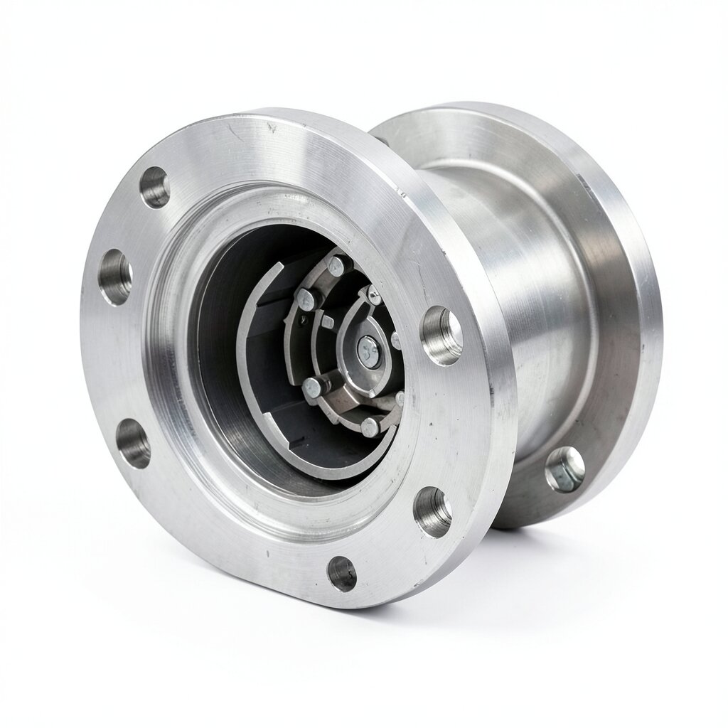
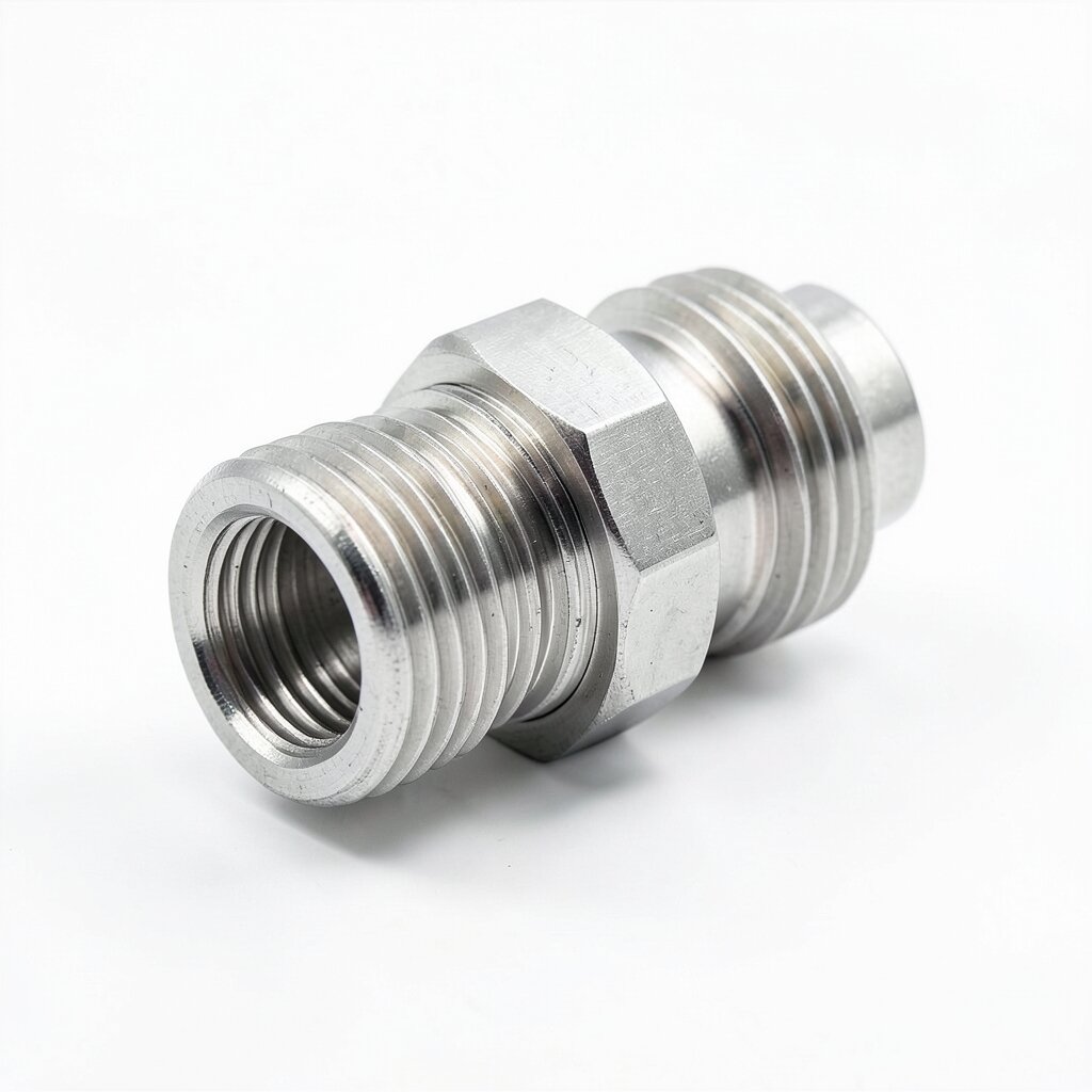
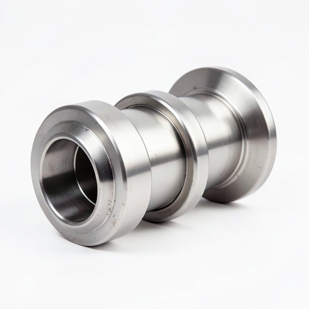
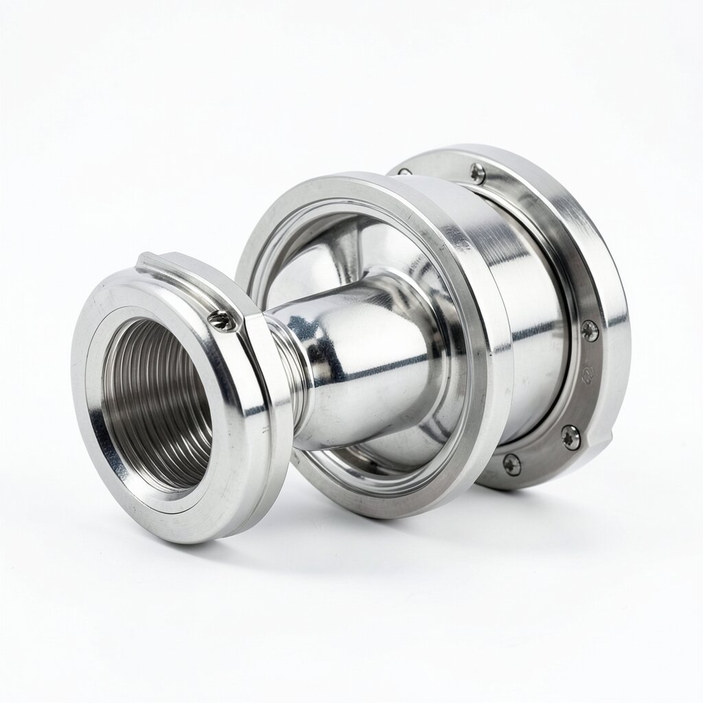
Bolt-in inline mixing element with ANSI / DIN / JIS flange ends — the most universal structural variant for chemical, water-treatment, and oil-and-gas plants where the cartridge must be removable for periodic inspection.
Product Overview
The flanged static mixer is the workhorse structural variant of the ywmixing product line. It consists of a cylindrical shell fitted with mating flanges on each end, containing a removable mixing-element cartridge. The flanged interface allows the entire assembly to be dropped into an existing pipe spool between two flanged connections and bolted in place, exactly like a pipe spool, strainer, or check valve. This is the connection type specified by approximately 70% of our industrial customers because it lets maintenance crews pull the cartridge without cutting the pipe or sending a hot-work crew to the field.
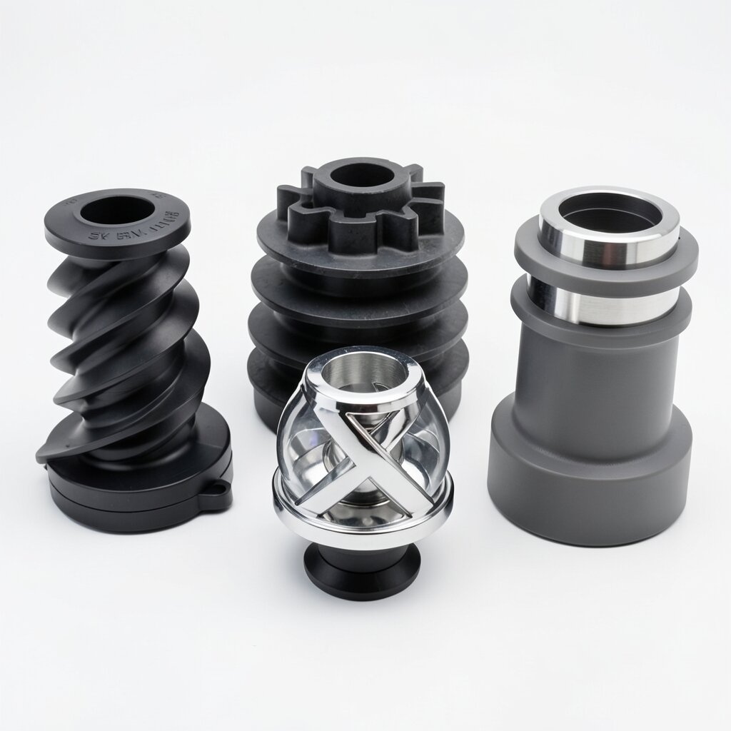
Inside the shell, the customer can specify any of the five mixing geometries (SV corrugated plate, SK helical, SX cross-bar, SH dual-channel, or SL single-X) so the connection style is fully decoupled from the mixing technology. A DN200 SS316L flanged mixer with an SK helical cartridge is one of the most common configurations in chemical dosing skids; a DN600 carbon-steel flanged mixer with an SV corrugated plate is the standard for municipal water treatment. The flanged variant therefore serves as the structural platform for the entire mixer family.
The unit is designed for bolted-service pressure ratings up to PN40 (40 bar) in carbon steel and PN16 (16 bar) in stainless steel, with temperature envelopes from -50°C to +300°C depending on material and gasket selection. Standard sizes span DN15 to DN600, and custom large-bore units up to DN1000 are built to order. Gasket face finishes are RF (raised face) by default, with RTJ (ring-type joint) and FF (flat face) available for special service.
Design Features
The flanged mixer housing is built as a flanged pipe spool with an internal cartridge retainer. The shell is rolled and seam-welded from plate or bar-stock pipe, then fitted with forged or plate-flange weld-necks at each end. The flange facing follows the customer-specified standard, and the bolt pattern is matched to the mating pipe flanges in the plant. A removable retainer ring or shoulder at each end of the shell holds the cartridge in place during operation but allows axial extraction when the downstream flange is unbolted.
The mixing cartridge is a stand-alone assembly that slides into the shell on a precision machined spigot. It carries the mixing elements (helical elements, plate pack, X-bars, or dual-channel core depending on the technology selected), the central alignment key, and the locating shoulders. When the operator unbolts the downstream flange and slides the cartridge out, the elements come with it as one piece — no loose parts, no dropped hardware inside the line. Cartridges are available in 1.4404 (316L), 1.4301 (304), Hastelloy C-276, and PTFE-lined carbon steel.
Gasket seating is machined to a Ra ≤ 1.6 μm finish and uses a spiral-wound graphite/filler gasket rated for the design pressure and temperature. For high-temperature cyclic service (above 200°C with daily start-up/shutdown), we recommend graphite-faced gaskets with a stainless inner and outer ring; for cryogenic service below -30°C, PTFE-jacketed gaskets are specified to retain seal at the reduced bolt load. All flanges are drilled and identified per the customer's piping class.
Pressure-containing components are designed in accordance with ASME B31.3 for process piping or EN 13445 for European installations, with a 1.5× design margin on burst and a 4× margin on fatigue. The housing carries a unique serial number, ASME U-stamp or PED CE-marking where applicable, and full MTR (mill test report) traceability for wetted parts.
Technical Specifications
| Parameter | Value |
|---|---|
| Connection Standard | ANSI B16.5 / DIN PN / JIS / GB / AWWA — Class 150, 300, PN10, PN16, PN25, PN40 |
| Pipe Diameter Range | DN15 to DN600 (custom DN1000 on request) |
| Pressure Rating | Up to PN40 (carbon steel) / PN16 (SS316L) / PN100 special |
| Temperature Range | -50°C to +300°C (metallic) / -10°C to +80°C (PTFE-lined) |
| Housing Material | SS304, SS316L, Carbon Steel SA-106 Gr.B, Hastelloy C-276, Duplex 2205 |
| Cartridge Material | Same as housing, or PTFE/PVDF-lined carbon steel |
| Mixing Elements | SV / SK / SX / SH / SL — customer selected |
| Flange Facing | RF (default), FF, RTJ, Tongue & Groove |
| Gasket Type | Spiral-wound graphite, PTFE, or graphite-clad stainless |
| Design Code | ASME B31.3, EN 13445, ASME B&PV Sec VIII (vessels) |
| Certification | PED CE, ASME U-stamp, ATEX on request |
| Flow Rate Range | 0.1 to 4,000 m³/h (size dependent) |
Frequently Asked Questions
Standard flange drillings include ANSI B16.5 Class 150 and Class 300, DIN PN10/PN16/PN25/PN40, JIS 10K/20K, and GB/T 9119. Custom flanges to ASME B16.47 Series A or AWWA C207 are available on request for large-diameter service.
Yes. The flanged housing uses a two-piece body or a flanged cartridge retainer, so the operator unbolts the end flange, slides the mixing cartridge out axially, inspects the elements, and reinstalls. Typical downtime is 30-60 minutes for a DN200 unit.
Standard carbon steel flanged mixers are rated to PN40 (40 bar at 120°C). SS316L housings carry a de-rated PN16 due to the lower allowable stress of the flange forging at elevated temperature. Higher classes up to PN100 are available on special order for HP chemical service.
Yes. The flanged joint absorbs differential thermal expansion between the mixer housing and the connected piping, and the cartridge is mounted with a sliding fit inside the housing to allow for axial growth. Specify graphite gaskets for cyclic service above 200°C.
Related Products