Welded Static Mixer
HP/HT Welded Inline Mixer
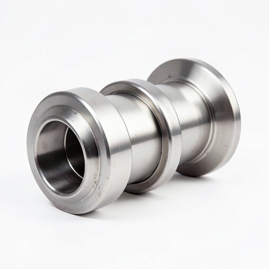
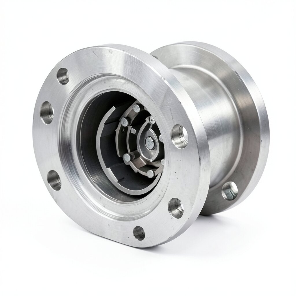
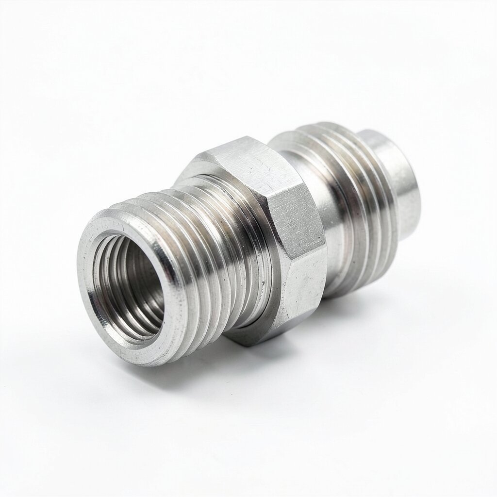
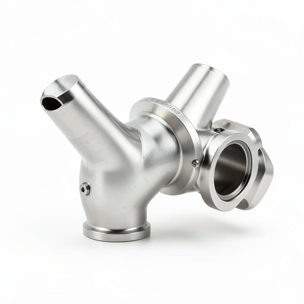
Permanent butt-welded inline mixer for high-pressure and high-temperature service — the structural variant of choice for refinery hydroprocessing, steam injection, and HP chemical reactors up to PN100 and 600°C.
Product Overview
The welded static mixer is the structural variant built for installations where the mixer is a permanent part of the piping and will not be removed for the life of the unit. It is fabricated as a rolled-and-welded shell with butt-weld ends prepared to ASME B16.25, and the mixing elements are welded to internal supports that are themselves attached to the shell wall. There are no flanges, no threaded joints, and no clamp ferrules — the mixer is welded into the line during construction and stays there.
This construction is mandatory for high-pressure and high-temperature service. The flange and threaded connections both rely on gaskets or thread sealants that have a temperature ceiling around 300-400°C and a pressure ceiling around PN40. Beyond those limits, the welded joint is the only mechanically reliable way to join a mixer into a process line. Hydroprocessing reactors, steam injection headers, and HP polyethylene reactors all use welded mixers for this reason.
The welded mixer is built in carbon steel (SA-516, SA-106, SA-335 P11/P22/P91) for the high-temperature envelope, in SS316L for chemical service, and in low-alloy steels for elevated-temperature petrochemical service. The shell wall thickness is calculated per ASME B31.3 with a 1.5× safety margin on burst, and all longitudinal and circumferential welds are 100% radiographed. The unit is supplied with a full MTR and ASME U-stamp or PED CE-marking where the project requires it.
Design Features
The welded housing is a cylindrical shell with two butt-weld-end preparations machined to ASME B16.25 (30° bevel, 1.6 mm land) for butt-welding into the line. For small-bore units (DN50-DN80), socket-weld ends per ASME B16.11 are available to simplify field installation. The shell is rolled from plate and longitudinally welded, then the two end prep rings are fitted and circumferentially welded. For high-pressure service above PN63, the housing is forged rather than fabricated to eliminate the longitudinal seam.
Inside the housing, the mixing element pack is retained by welded support rings. For SV plate geometry, the plate stack is welded to a central alignment pin and supported at each end by welded ring-stiffeners that are themselves attached to the shell wall with a fillet weld. The element pack is therefore a permanent part of the pressure boundary. For SK helical geometry, the elements are welded end-to-end to form a continuous twisted ribbon, and the upstream end is welded to a retainer plate; this construction tolerates thermal expansion because the helix is free to slide in the axial direction at the downstream end.
For high-temperature service above 400°C, the housing is stress-relieved after welding per ASME B31.3. For service in the creep range (above 500°C, e.g., P91 in steam lines), the housing is normalized and tempered, and the weld procedure includes a pre-heat and post-weld heat treatment (PWHT) at 730-760°C. Hardness surveys are performed on the HAZ of every weld to confirm the 22 HRC NACE MR0175 limit for sour service.
Inspection access for the welded mixer is provided by borescope ports in the upstream and downstream pipe spools. These 1" NPT ports are typically supplied by the customer; on request we will factory-weld a 1" NPT coupling to the housing at 90° to the flow, for periodic visual inspection of the element pack. The welded mixer can also be inspected by RT or UT of the housing welds per the customer's inspection plan.
Technical Specifications
| Parameter | Value |
|---|---|
| Connection Standard | Butt-weld (ASME B16.25) or Socket-weld (ASME B16.11) ends |
| Pipe Diameter Range | DN50 to DN1000 (custom larger on request) |
| Pressure Rating | PN100 standard, PN63 (SS316L), PN250 special |
| Temperature Range | -50°C to +600°C (low-alloy steel) / -50°C to +450°C (SS316L) |
| Housing Material | SA-516 Gr.70, SA-106 Gr.B, SA-335 P11/P22/P91, SS316L, SS304 |
| Mixing Element | SK helical (default) or SV plate — welded in housing |
| Wall Thickness | Calculated per ASME B31.3 with 1.5× safety margin |
| Weld Preparation | 30° bevel + 1.6 mm land (B16.25) or socket (B16.11) |
| NDT | 100% RT on longitudinal and circumferential seams |
| Heat Treatment | Stress-relief per B31.3; PWHT for creep-range service |
| Design Code | ASME B31.1, B31.3, EN 13445 |
| Certification | ASME U-stamp, PED CE, NACE MR0175 (sour service) |
Frequently Asked Questions
Welded mixer housings are rated to PN100 (100 bar) as standard in carbon steel, with a maximum allowable pressure of 165 bar at 250°C for DN50-DN200 sizes. SS316L housings carry a de-rated PN63 due to the lower allowable stress of the austenitic steel. Higher classes up to PN250 are built to special order for HP refinery service.
No. The welded mixer is a permanent installation. Inspection is performed with borescopes through the inlet/outlet pipe or by radiographic examination of the housing welds. For applications requiring cartridge removal, the flanged or tri-clamp variant should be selected instead.
Default weld prep is a 30° bevel with a 1.6 mm land, per ASME B16.25. Socket-weld ends (ASME B16.11) are available for small-bore DN50-DN80 service. All weld preps are cleaned, degreased, and protected with a plastic cap for shipping.
Yes. Welded mixers for sour service (NACE MR0175) are produced from HIC-resistant steel plate (e.g., SA-516 Gr.70 normalized) with hardness limited to 22 HRC max. Weld procedures are qualified per ASME Section IX, and the housing is 100% radiographed. NACE certificate is supplied with the unit.
Related Products