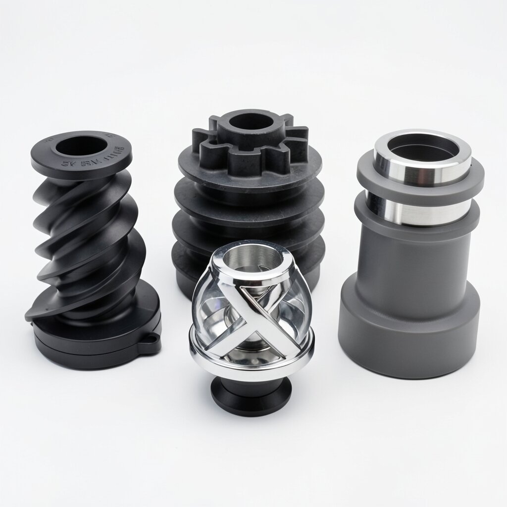
Sanitary T-Type Mixer
Tri-Clamp Side-Injection Mixer
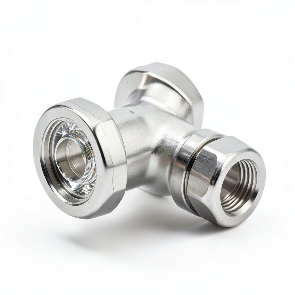
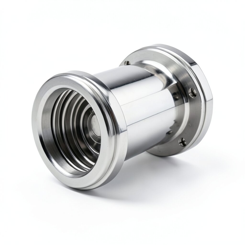
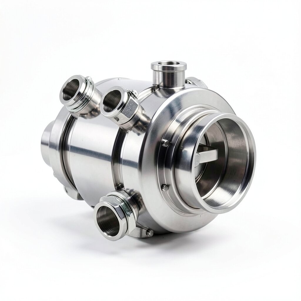
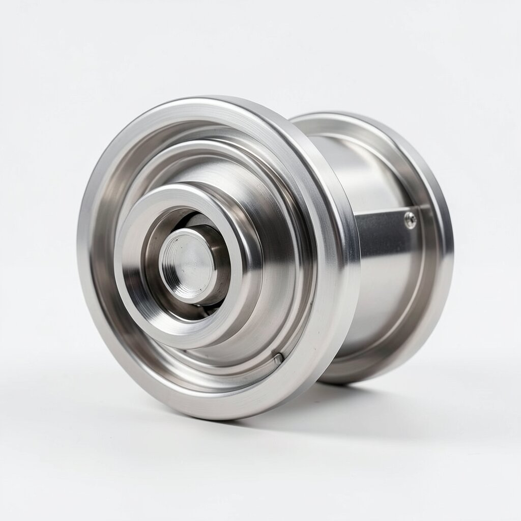
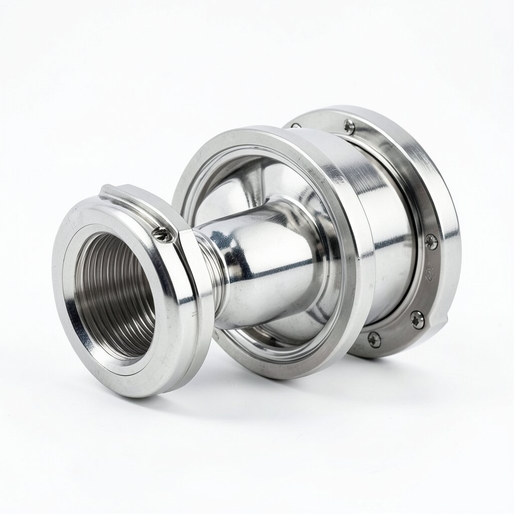
Sanitary inline mixer with an integrated 90° tri-clamp side tee — for chemical, WFI, or clean-steam injection into a CIP/SIP loop without the dead leg of a field-fabricated tee-and-pipe assembly.
Product Overview
The sanitary T-type mixer is a straight-through mixer with an integrated 90° side tee at the upstream end. The side tee accepts a chemical, WFI, clean-steam, or buffer injection line via a standard tri-clamp ferrule, and discharges the injected stream directly into the first mixing element inside the housing. The integrated tee eliminates the dead leg that would exist in a field-fabricated tee + pipe spool + mixer assembly — a dead leg that, in a CIP loop, would be a documented source of product carryover and bioburden risk.
The T-type mixer is the sanitary version of the Y-type industrial mixer. The geometry and the operating principle are the same; what differs is the surface finish (Ra ≤ 0.8 μm polished, with electropolish available for bioprocess), the connection standard (tri-clamp throughout, no threaded or welded joints), and the documentation (full MTR, surface-finish report, passivation certificate, USP Class VI gaskets). The mixer is qualified to ASME BPE, 3-A 18-03, and EHEDG Doc 8, and the validation report covers drainability, cleanability, and SIP compatibility.
The unit is available in DN25 to DN100 main-line sizes, with the side tee sized at 1/3 to 1/2 of the main line (typically DN15-DN50). The side tee is at 90° to the main flow — the standard sanitary geometry — but 45° side tees are available on request for high-momentum injection (e.g., clean steam into a WFI line). The housing is SS316L throughout, with the element pack in SS316L SV plate or SK helical geometry depending on the application.
Design Features
The T-type housing is a single SS316L forging with the main-line bore and the side-tee bore machined and polished in one setup. This guarantees the same surface finish on both bores and eliminates any weld HAZ at the tee intersection. For sizes above DN80, where a single forging becomes uneconomical, the housing is fabricated from rolled SS316L plate with the side tee welded in using a full-penetration TIG weld that is then ground and re-polished to the same Ra finish as the rest of the housing.
The side tee is positioned so its bore is tangent to the main-line bore at the upstream end of the first mixing element. This ensures the injected stream is delivered directly into the element, with no dead zone at the intersection. The tangent entry also creates a slight pre-rotation of the injected stream, which improves the mixing efficiency of the first element by 10-20% compared to a perpendicular entry.
Inside the housing, the mixing element pack is positioned immediately downstream of the side tee. For SV plate technology, the first plate sits 5-10 mm downstream of the side-tee outlet, with the plate pack extending 4-8 elements along the housing. For SK helical technology, the first helical element is welded to an internal shoulder just downstream of the side tee, with the helix extending 4-6 elements along the housing.
All wetted materials are documented for FDA and USP compliance. The SS316L housing is supplied with a 3.1 MTR and a ferrite report. The EPDM gaskets on both the main-line and side-tee connections are USP Class VI tested and supplied with a lot-traceable certificate. The mixer is passivated per ASTM A967 and delivered in a Class 100 cleanroom double-bag. For bioprocess service, the mixer is supplied with an SF1 (Ra ≤ 0.51 μm) or SF4 (Ra ≤ 0.38 μm) electropolish.
Technical Specifications
| Parameter | Value |
|---|---|
| Main-Line Connection | Tri-clamp per ISO 2852 / DIN 32676 / ASME BPE / BS 4825-3 |
| Side-Tee Connection | Tri-clamp per same standard, 90° to main flow (45° on request) |
| Main-Line Diameter | DN25 (1") to DN100 (4") |
| Side-Tee Diameter | DN15 (1/2") to DN50 (2") — typically 1/3 to 1/2 of main |
| Pressure Rating | PN16 (10 bar at 25°C) for SS316L standard |
| Temperature Range | -10°C to +130°C (EPDM) / -20°C to +200°C (PTFE) |
| Housing Material | SS316L (≤ 0.030% C, ASTM A479) — forged or fabricated |
| Mixing Element | SV plate (default) or SK helical — SS316L |
| Surface Finish (Wetted) | Ra ≤ 0.8 μm mechanical (default) / Ra ≤ 0.4 μm electropolish |
| Gasket | EPDM USP Class VI (default), FKM, PTFE, Silicone |
| Certifications | ASME BPE, 3-A 18-03, EHEDG Doc 8, FDA, USP Class VI |
| Side-Tee Velocity | 1.5-3.0 m/s (recommended for chemical injection) |
Frequently Asked Questions
The T-type mixer integrates the side tee into the housing at the factory, so the injected stream is delivered directly into the first element with no dead leg. A field-fabricated tee + mixer assembly has a 3-5D straight pipe between the tee and the mixer, which creates a dead zone where the injected chemical can pool and degrade. The integrated T-type eliminates this dead zone and gives better mixing precision.
The side tee is typically 1/3 to 1/2 of the main line diameter. For a DN50 main line, the side tee is typically DN15-DN25, sized to give a 1.5-3.0 m/s injection velocity at the maximum chemical flow rate. The side tee ferrule is the same tri-clamp standard as the main line, so the chemical line can be connected with a standard tri-clamp joint.
Yes. The side tee is drilled at 90° to the main flow, and the inside of the tee is polished to the same Ra ≤ 0.8 μm finish as the main housing. When the line is drained, gravity pulls all residual fluid from the side tee to the main line and out the outlet. The drainability is verified by the EHEDG Doc 2 test, and the certificate is supplied with the unit.
Yes. The T-type mixer is suitable for clean steam injection at 121-130°C, typically used for SIP (steam-in-place) of the downstream piping. The housing is rated for the corresponding steam pressure (typically 2-3 bar saturated), and the side tee ferrule is dimensioned to match the clean steam supply line. The mixer element is the high-temperature SS316L helical (SK) for steam service.
Related Products