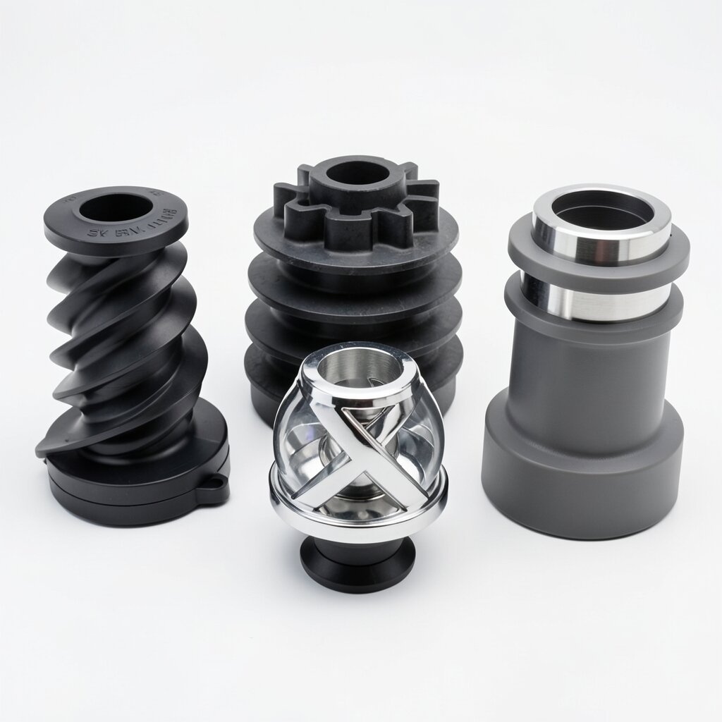
Sanitary Distributor-Integrated Mixer
Multi-Port Sanitary Distributor
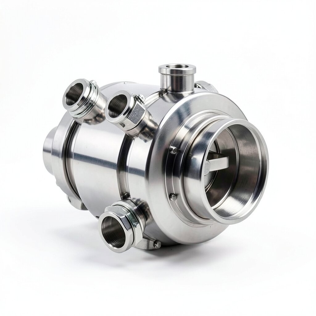
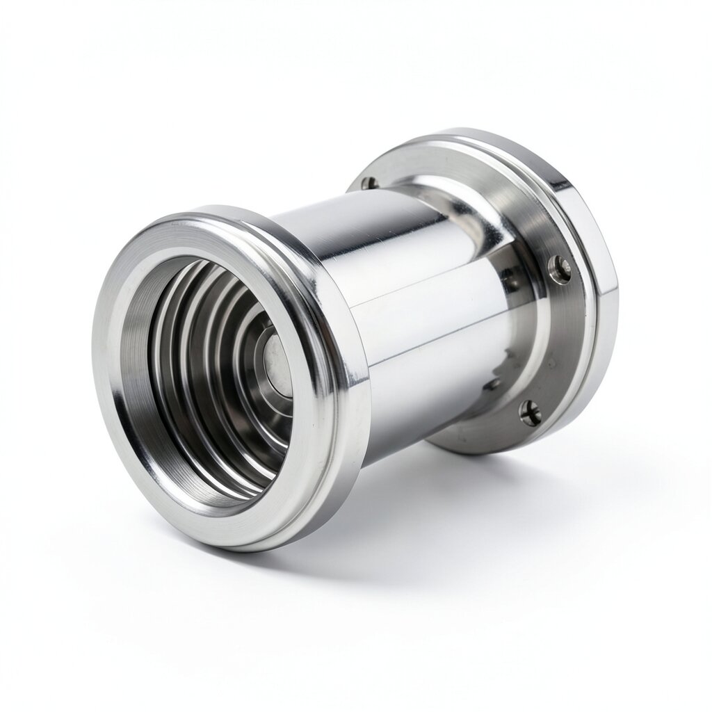
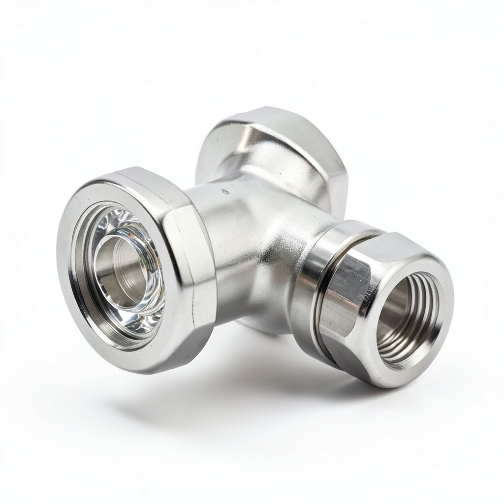
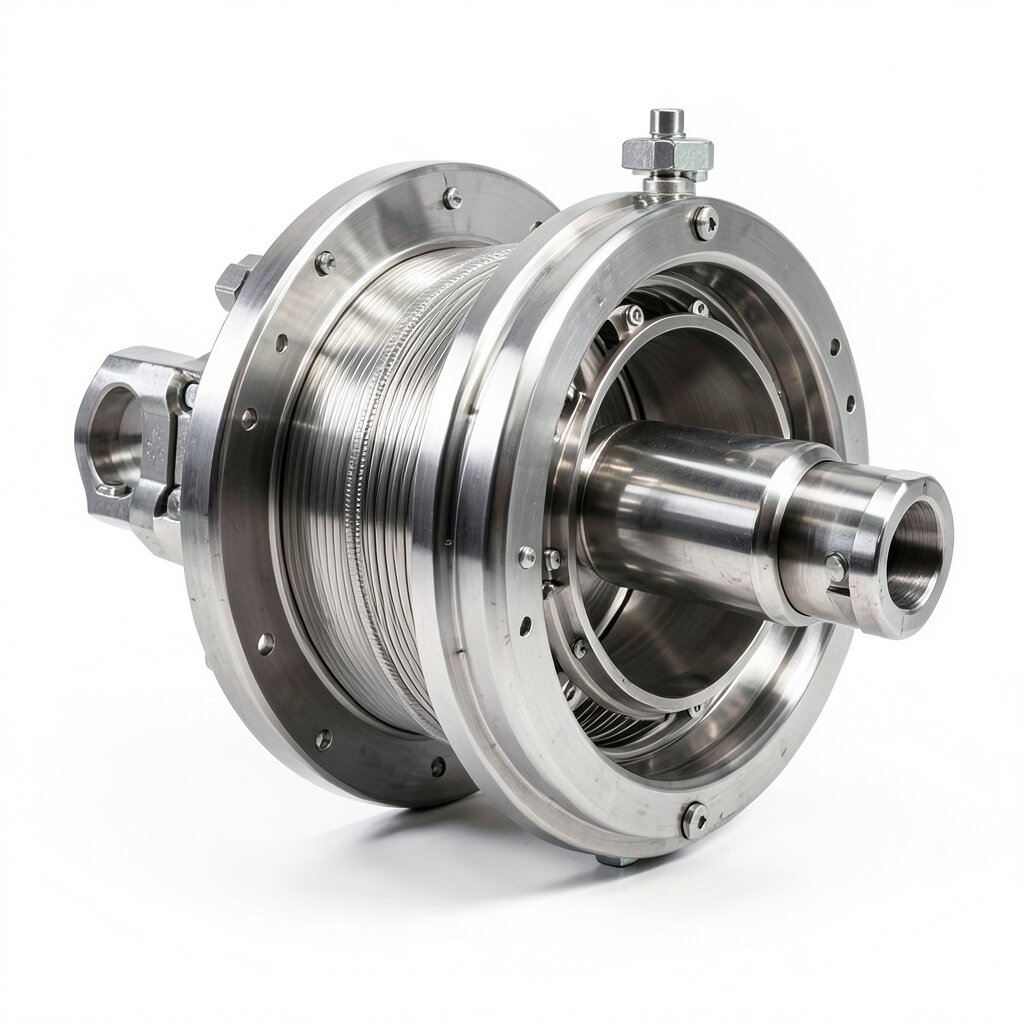
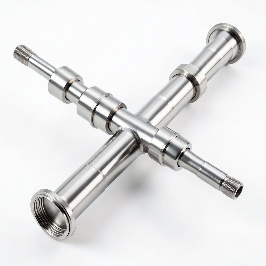
Sanitary inline mixer with a built-in distribution manifold — the structural variant for blending one primary stream with multiple secondary streams (buffer concentrate, acid, base, WFI) in a single drainable SS316L housing.
Product Overview
The sanitary distributor-integrated mixer is the most complex of the sanitary structural variants. It is built around a true distribution manifold: a separate chamber at the upstream end of the housing that accepts 2, 3, or 4 inlet streams through individual tri-clamp ferrules, and delivers the combined flow to the mixing element through a single outlet. The manifold equalizes the pressure and velocity of the incoming streams so they enter the mixing element as a single homogeneous flow, which gives a more uniform mixing result than separate side-tee injection points.
The distributor-integrated mixer is the natural choice for multi-component blending in pharmaceutical, biotech, and food processing. The classic example is buffer make-up, where the buffer concentrate, the WFI diluent, and the pH-adjustment reagents (acid + base) are all added in a single mixer to produce the final buffer. The integrated manifold eliminates the need for a separate distribution piping manifold upstream of the mixer, saving both installation cost and floor space in the buffer make-up skid.
The unit is available in DN50 to DN150 main-line sizes, with the inlet ports sized to match the individual stream flow rates. The mixing element is typically SV plate technology for fine chemical blending, or SK helical for buffer/media preparation. The element pack is removable for cleaning and inspection, and the manifold is fully drainable per EHEDG Doc 2. The polished surface (Ra ≤ 0.8 μm default, Ra ≤ 0.4 μm electropolish) supports CIP and SIP regimes standard in pharmaceutical processing.
Design Features
The distributor-integrated housing is a two-chamber SS316L fabrication: an upstream distribution manifold and a downstream mixing element housing, joined by a flanged connection that allows the manifold to be removed for cleaning and inspection. Both chambers are polished internally to Ra ≤ 0.8 μm, and the flange connection is gasketed with EPDM (USP Class VI) so the entire wetted surface can be CIP-cleaned in a single loop.
The manifold is a forged or fabricated SS316L body with 2, 3, or 4 inlet ferrules. The inlets are positioned at 90° intervals around the manifold circumference to ensure even distribution of the incoming streams. The manifold outlet is a single ferrule at the center of the downstream face, which mates with the mixing-element housing. The internal volume of the manifold is sized to give 0.5-1.0 seconds of residence time at the maximum flow rate, which is enough to equalize the pressure and velocity of the incoming streams.
Inside the mixing-element housing, the element pack is positioned immediately downstream of the manifold outlet. For SV plate technology, the first plate sits 5-10 mm downstream of the manifold outlet, with the plate pack extending 4-8 elements along the housing. For SK helical technology, the first helical element is welded to an internal shoulder just downstream of the manifold outlet, with the helix extending 4-6 elements along the housing.
All wetted materials are documented for FDA and USP compliance. The SS316L housing and manifold are supplied with a 3.1 MTR and a ferrite report. The EPDM gaskets on the manifold and the main-line connections are USP Class VI tested. The mixer is passivated per ASTM A967 and delivered in a Class 100 cleanroom double-bag. For bioprocess service, the mixer is supplied with an SF1 (Ra ≤ 0.51 μm) or SF4 (Ra ≤ 0.38 μm) electropolish.
Technical Specifications
| Parameter | Value |
|---|---|
| Main-Line Connection | Tri-clamp per ISO 2852 / DIN 32676 / ASME BPE / BS 4825-3 |
| Inlet Connections | Tri-clamp, 2-4 ports, 90° spacing around manifold |
| Main-Line Diameter | DN50 (2") to DN150 (6") |
| Inlet Diameter | DN15 (1/2") to DN50 (2") — per port, individually sized |
| Pressure Rating | PN16 (10 bar at 25°C) for SS316L standard |
| Temperature Range | -10°C to +130°C (EPDM) / -20°C to +200°C (PTFE) |
| Housing Material | SS316L (≤ 0.030% C, ASTM A479) — fabricated |
| Mixing Element | SV plate (default) or SK helical — SS316L |
| Surface Finish (Wetted) | Ra ≤ 0.8 μm mechanical (default) / Ra ≤ 0.4 μm electropolish |
| Gasket | EPDM USP Class VI (default), FKM, PTFE, Silicone |
| Manifold Residence Time | 0.5-1.0 seconds at maximum flow rate |
| Certifications | ASME BPE, 3-A 18-03, EHEDG Doc 8, FDA, USP Class VI |
Frequently Asked Questions
The distributor-integrated mixer uses a true distribution manifold (a separate chamber that splits one inlet stream into several), while the multi-inlet mixer uses several separate side-ports that each accept their own stream. The distributor version is used when one feed stream needs to be distributed across multiple injection points inside the mixer; the multi-inlet version is used when several different chemicals need to be injected at different points.
Standard configurations support 2, 3, or 4 inlet streams. Each stream is delivered via a tri-clamp ferrule, and the distribution manifold splits or combines the streams before they enter the mixing element. Above 4 streams, the manifold becomes uneconomical and the customer should use staged mixers in series.
Yes. The manifold is designed with a 1-2° slope toward the mixing element, and the internal surfaces are polished to the same Ra ≤ 0.8 μm finish as the main housing. When the line is drained, gravity pulls all residual fluid from the manifold into the mixing element and out the outlet. The drainability is documented per EHEDG Doc 2.
The most common application is the blending of a primary stream with multiple secondary streams (e.g., WFI + buffer concentrate + acid + base) into a single homogeneous outlet. The mixer is also used for in-line dilution of concentrates, where one stream of concentrate is distributed into multiple WFI streams and the combined outlet is the diluted product.
Related Products