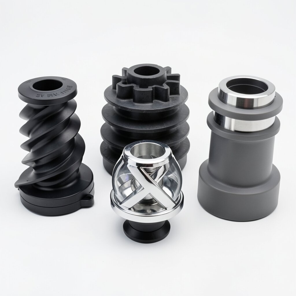
SH Type Dual-Channel Static Mixer
Dual-Channel Static Mixer
Two parallel helical channels with redistribution chambers — for clean, high-viscosity media where color or concentration uniformity must be controlled to 1-2 mm scale.
Product Overview
The SH type dual-channel static mixer addresses a specific class of process problems that sit awkwardly between the SK and the SX. The fluids in question are highly viscous — often 50,000 to 500,000 cP — but the mixing requirement is not so much "blend two streams together" as "guarantee that the concentration at every point across the pipe cross-section is within a defined tolerance." Color masterbatch dosing into polymer melt, pigment dispersion in synthetic fiber spinning solution, and active-ingredient incorporation into pharmaceutical ointment all share this profile. The dual-channel geometry of the SH, with its internal helical vanes and redistribution chambers between elements, is purpose-built for it.
Where the SK uses a single twisted blade that occupies the full pipe cross-section, the SH divides the flow into two parallel channels. Each channel contains its own helical vane, and the two channels rotate the fluid in opposite directions. At the end of each element, the two channels are recombined in a redistribution chamber, then split again into the next pair of channels — but rotated 90° relative to the first pair. This is what gives the SH its defining characteristic: a very narrow, very predictable residence time distribution, even at viscosities where the SK and SX would produce broader distributions because of their less-constrained geometries.
The SH is a small-flow, small-diameter model. It is manufactured from DN15 to DN200, which corresponds to flow rates of roughly 0.01 to 50 m³/h. This size limitation is deliberate — at larger diameters, the redistribution chambers become too large for the channel-equalization effect to work, and the SK becomes the more appropriate choice. The SH is also restricted to clean media. The dual channels have a narrower free cross-section than the SK blade, and any particulate above 0.5 mm will accumulate in the redistribution chambers over time, unbalancing the two channels and degrading the mixing performance.
Working Principle
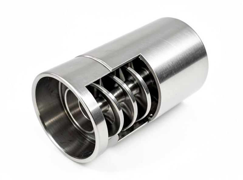
An SH element consists of two parallel semicircular channels formed by a divider plate running along the pipe axis, with a helical vane fitted inside each channel. The vane pitch is typically 30-50 mm, and the channel width is 40-50% of the pipe diameter. The element length is 1.5-2.0D — longer than the SK's 1.0-1.5D because the dual-channel geometry requires more axial distance to produce the same number of theoretical mixing stages.
Fluid entering the SH is split immediately into the two channels. Within each channel, the helical vane induces a swirl component, but unlike the SK's 180° twist, the swirl in each SH channel is only 60-90° over the element length. The two channels are designed to swirl in opposite directions, so when the fluid reaches the end of the element, the two streams have similar but counter-rotating velocity profiles. The redistribution chamber then merges them. Because the two streams have been processed identically (just in mirror-image channels), their composition profiles are matched — and the merged stream has a much more uniform cross-sectional composition than either stream would have alone.
The next element is rotated 90° from the first, so the two channels now point "up" and "down" instead of "left" and "right." The fluid is split again, and the same helical induction occurs. Over 4-6 elements, the fluid has been processed 4-6 times by the matched-channel system, and the residence time distribution narrows to within σX ≤ 1-5%. The 1-2 mm dispersion precision quoted in our specifications refers to the spatial scale of concentration fluctuations in the mixed stream — not to droplet size, since the SH is typically used for miscible-liquid blending rather than emulsification.
The redistribution chambers are the key design feature that distinguishes the SH from a simple "two parallel SK elements" configuration. Without the chambers, the two channels would slowly develop different pressure drops (because of slight manufacturing asymmetries and because the fluid properties are not perfectly matched), and one channel would end up carrying most of the flow. The chambers equalize the pressure between elements, ensuring that both channels continue to operate near their design flow split throughout the life of the mixer.
Technical Specifications
| Parameter | Value |
|---|---|
| Internal Structure | Dual parallel channels with internal helical vanes; adjacent units offset 90°; redistribution chambers between elements |
| Dispersion Precision | 1-2 mm spatial scale of concentration variation (not droplet size) |
| Viscosity Range | 100 cP to 1,000,000 cP (clean, high-viscosity media) |
| Pressure Drop | Moderate; 3-6 velocity heads per element + chamber losses |
| Non-Uniformity Coefficient | σX ≤ 1-5% with 4-6 elements (depending on viscosity and L/D) |
| Material Options | SS304, SS316L, Carbon Steel, PVC, PP, Hastelloy C-276 |
| Connection Types | Flange (ANSI / DIN / JIS), Threaded (NPT / BSP), Welded, Tri-Clamp |
| Temperature Range | -50°C to +300°C (metallic) / -10°C to +80°C (PVC/PP) |
| Pipe Diameter Range | DN15 to DN200 (small-flow model by design) |
| Flow Rate Range | 0.01 to 50 m³/h (model and pipe-size dependent) |
| Clogging Risk | Moderate — restricted to clean media; particles < 0.5 mm |
| Internal Structure | Dual-channel helical Corrugated plates Helical twist Crossed bars Single-X bars |
| Dispersion Precision | 1-2 mm 1-2 μm ≤ 10 μm 2-5 μm Medium |
| Max Viscosity (cP) | 1,000,000 100 1,000,000 10,000 10 (or polymer) |
| Pipe Diameter | DN15-DN200 DN15-DN1000 DN15-DN500 DN25-DN800 DN15-DN600 |
| Clogging Risk | Moderate High Lowest Moderate Low |
| Best For | High-viscosity clean Fine dispersion High-viscosity Mid-range Heat transfer |
Frequently Asked Questions
Both share a 1,000,000 cP viscosity ceiling, but the SH uses dual parallel channels with internal helical vanes and redistribution chambers between elements. The result is coarser dispersion (1-2 mm vs SK's ≤10 μm) but a more uniform, predictable residence time distribution that is critical for color matching and pharmaceutical dosing.
The SH is restricted to DN15-DN200 and the dual channels have a narrower free cross-section than the SK's open blade geometry. Particulates above 0.5 mm will accumulate in the redistribution chambers and cause channel imbalance.
Color masterbatch dosing into polymer melt at 5,000-50,000 cP typically uses 4-6 SH elements to reach ΔE color difference below 0.5. The redistribution chambers between elements are what allow the SH to deliver this precision despite operating in a viscosity range where most other static mixers fail.
Yes. The SH in sanitary SS316L with Ra ≤ 0.8 μm finish and tri-clamp connections is widely used for pharmaceutical ointments, creams, and gels at 10,000-500,000 cP. The dual channels are self-draining and CIP-compatible.
Because the SH is restricted to small pipe diameters (DN15-DN200), the practical flow rate range is 0.01 to 50 m³/h. The SH is intentionally a small-flow, high-precision model — for higher flow rates the SK or SX should be used.
Related Products