SD Type Perforated Plate Static Mixer
Perforated Plate Static Mixer
Multi-orifice perforated plate mixer for medium-viscosity service — 5-10 μm dispersion precision, σX ≤ 5%, with broad material compatibility and DN15-DN600 coverage.
Product Overview
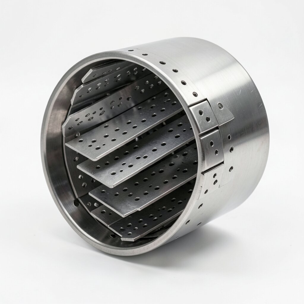
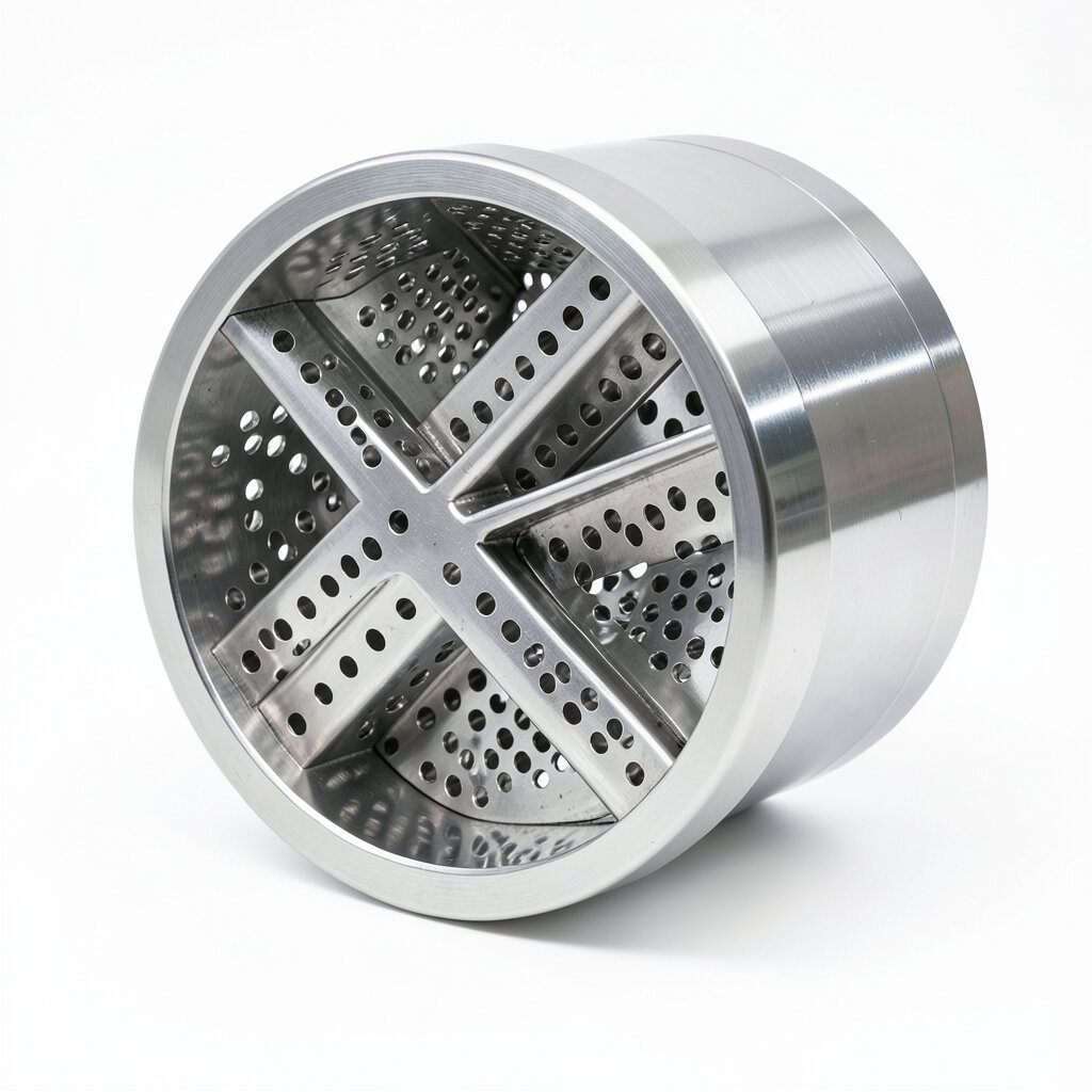
The SD type perforated plate static mixer is the general-purpose workhorse of the ywmixing plate-mixer family. Inside a cylindrical housing, multiple flat plates — each drilled or punched with a regular array of circular holes — are stacked at fixed spacing, typically 1.0-2.5 plate diameters apart. The hole pattern, plate thickness, open-area fraction, and number of plates are the four design parameters that the engineer tunes to match the process duty. The result is a robust, low-clag mixer that delivers 5-10 μm dispersion precision with σX ≤ 5% over a viscosity range of 1-10,000 cP and a pipe range of DN15 to DN600.
Where the SV corrugated plate model targets sub-5 μm precision in clean, low-μ fluids and the SDB dual-perforated-plate model handles fouling service with fibers and particles, the SD occupies the middle ground: it has larger flow channels (8-25 mm typical) than the SV but tighter geometry than the SDB, giving it a better dispersion precision than helical twist mixers of comparable L/D while remaining tolerant of occasional particulate excursions up to 2-3 mm. For most chemical-dosing, pH-adjustment, and oil-water blending applications in water treatment, fine chemicals, and refinery service, the SD is the first model specified.
Mechanically, the SD is also one of the simplest mixers to manufacture, inspect, and clean. Each plate is a flat disc that can be lifted out of the housing individually, so a fouled or damaged plate is replaced in minutes rather than the hours required to dismantle a corrugated-plate bundle. This has made the SD the preferred choice in plants where maintenance windows are short and where the unit must be opened for routine inspection every 3-6 months.
Working Principle
The mixing action of the SD is generated by the repeated radial and axial redirection of fluid as it passes through successive perforated plates. Each plate presents an array of circular orifices — typical diameters 4-15 mm, arranged in an equilateral-triangular pitch with an open-area fraction of 30-50%. As the fluid approaches a plate, the cross-section is suddenly reduced to the total hole area, accelerating the flow to 1.5-2.5× the upstream velocity. The jets exiting the orifices impinge on the downstream plate (or, at the end of the housing, on the bulk fluid), where the radial velocity component of each jet crosses the adjacent jets and produces a vigorous turbulent mixing zone. Subsequent plates repeat the process with the holes rotated by 45-90° to the previous plate, ensuring that streamlines are reoriented on every pass.
Quantitatively, the per-plate pressure drop is governed by the standard orifice equation Δp = ½·ρ·v²·K, where the loss coefficient K is in the range 1.5-2.5 for a single perforated plate. For a 6-plate housing the cumulative K is approximately 9-15, giving a total pressure drop of 0.15-0.35 bar at 2 m/s water service in a DN100 unit. In the turbulent regime (Re > 4,000 based on orifice diameter), the mixing is dominated by eddy breakup and the dispersion precision is 5-10 μm. In the laminar regime (Re < 2,300), the jets lose coherence quickly and the mixing mechanism shifts to the viscous folding of stream tubes between plates, producing dispersions of 8-15 μm but still adequate for most neutralization and dosing applications.
Two design ratios govern sizing. The first is the open-area ratio α = Aholes / Apipe, typically 0.30-0.50. Lower α values give finer dispersion but higher pressure drop; higher α values allow larger particulates to pass but degrade mixing quality. The second is the plate spacing ratio β = s/d, where s is the inter-plate distance and d is the hole diameter, typically 1.0-2.5. Smaller β produces a more compact mixer with higher shear at each plate; larger β allows the jets to redevelop and is preferred when the bulk fluid is viscous. A correctly sized SD mixer will keep Re > 4,000 at the design flow rate to maintain turbulent operation; for Re between 2,300 and 4,000, the engineer should add 1-2 plates to compensate for the partial loss of eddy-driven mixing.
Technical Specifications
| Parameter | Value |
|---|---|
| Internal Structure | Stacked flat plates with circular-hole arrays; plates rotated 45-90° between stages |
| Hole Diameter Range | 4-15 mm standard; custom 2-25 mm available |
| Open-Area Fraction | 30-50% (typical); 25-60% (extended range) |
| Plate Spacing | 1.0-2.5 × hole diameter |
| Plate Count | 4-10 standard housings |
| Dispersion Precision | 5-10 μm (turbulent) / 8-15 μm (laminar) |
| Viscosity Range | 1-10,000 cP (kinematic), 10⁴ cP upper limit |
| Pressure Drop | 0.15-0.35 bar typical at 2 m/s water in DN100; scales with v² |
| Non-Uniformity Coefficient | σX ≤ 5% (standard design); ≤ 3% with extended L/D |
| Material Options | SS304, SS316L, Carbon Steel (PTFE/rubber lined), PVC, PP |
| Connection Types | Flange (ANSI / DIN / JIS), Threaded (NPT / BSP), Welded |
| Temperature Range | -50°C to +300°C (metallic) / -10°C to +80°C (PVC/PP) |
| Pipe Diameter Range | DN15 to DN600 |
| Flow Rate Range | 0.1 to 1,800 m³/h (model and pipe-size dependent) |
| Clogging Risk | Low to moderate; channel width 8-25 mm; particulate tolerance 2-3 mm |
| Internal Structure | Perforated plates Corrugated plates Dual perforated plates Helical twist Crossed bars |
| Dispersion Precision | 5-10 μm 1-2 μm 5-15 μm ≤ 10 μm 2-5 μm |
| Max Viscosity (cP) | 10,000 100 100,000 1,000,000 10,000 |
| Pipe Diameter | DN15-DN600 DN15-DN1000 DN25-DN600 DN15-DN500 DN25-DN800 |
| Clogging Risk | Low-moderate High Lowest Lowest Moderate |
| Particulate Tolerance | 2-3 mm < 0.5 mm 5-10 mm 5-10 mm 2-3 mm |
| Best For | General medium-μ Fine dispersion Fouling service High-viscosity Mid-range reactions |
Frequently Asked Questions
SD type mixers handle medium-viscosity fluids with kinematic viscosity ≤ 10,000 cP (10⁴ cP). Above this, the open-area fraction of the perforated plate is reduced by the boundary layer growth and pressure drop becomes prohibitive.
The SV uses sinusoidal corrugations producing 1-2 μm dispersion but with 2-5 mm channel width that clogs easily. The SD uses drilled or punched circular holes in flat plates, providing 8-25 mm channel width, 5-10 μm dispersion precision, and far higher tolerance to minor particulate.
Pressure drop scales with the square of velocity and the number of plates. A standard 6-plate DN100 housing at 2 m/s water service loses 0.15-0.35 bar. The loss coefficient K per plate is approximately 1.5-2.5 depending on hole diameter and pitch.
Yes. SD mixers are commonly used for low-pressure gas blending (combustion air, flue gas conditioning, biogas upgrading) at superficial velocities of 5-25 m/s. The plate geometry is well suited to gas service because the open area prevents liquid dropout and condensate accumulation.
Standard SD housings contain 4 to 10 perforated plates. The housing L/D ratio typically falls between 3 and 8, with the number of plates selected to achieve the target coefficient of variation σX ≤ 5% at the design flow rate.
Related Products