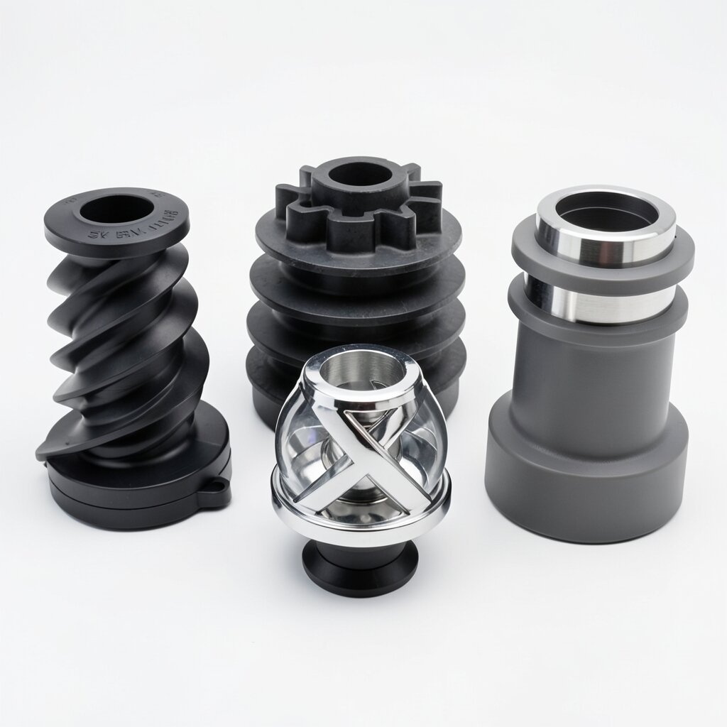
Color-Mixing Nozzle Dimensions
Standard Sizes & Fittings
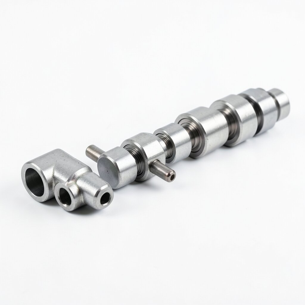
Standard sizes, thread options, and fitting data for the ywmixing color-mixing nozzle range — use this chart to select the correct nozzle for your injection molding machine.
How to Read the Dimension Chart
Every injection molding machine specifies its nozzle interface by three numbers: the draw-in thread (the threaded connection to the barrel), the tip radius (the spherical seat that contacts the sprue bushing), and the melt channel diameter (the bore size). The ywmixing nozzle range covers all three across four thread sizes and five melt channel sizes. When ordering, you need only supply these three values — the factory matches element count, overall length, and heater rating to your machine's melt capacity and shot size. The charts below give the standard range; non-standard thread pitches, longer nozzles, and multi-zone heating are available on request.
Thread and Bore Sizes
| Machine Clamp Range | Draw-In Thread | Melt Channel (Bore) | Standard Length | Tip Radius |
|---|---|---|---|---|
| 50-150 tonne | M80 × 2 | DN20-DN30 | 5D (100-150 mm) | R5 / R7.5 |
| 150-350 tonne | M95 × 2 | DN30-DN45 | 5D-6D (150-270 mm) | R7.5 / R10 |
| 350-700 tonne | M110 × 2 | DN45-DN60 | 6D (270-360 mm) | R10 / R12.5 |
| 700-1,500 tonne | M125 × 2 | DN60-DN80 | 6D-7D (360-560 mm) | R12.5 / R15 |
| 1,500+ tonne (flanged) | ANSI/DIN flange | DN80-DN150 | 7D-10D (560-900 mm) | R15 / custom |
Element Configuration by Bore Size
Mixing performance scales with the number of elements and their twist angle. The standard configuration table below gives the factory default for each bore size. For thin-wall parts or demanding color consistency, order the "high-division" option with two additional elements. For filled compounds, order the anti-clog geometry (270° pitch, wider clearance).
| Melt Channel | Standard Elements | Twist / Element | Flow Divisions | Pressure Drop (est.) |
|---|---|---|---|---|
| DN20 | 6 | 180° | 64 | 3-5 MPa |
| DN30 | 6 | 180° | 64 | 3-6 MPa |
| DN45 | 6 | 180° | 64 | 4-7 MPa |
| DN60 | 8 | 180° | 256 | 5-8 MPa |
| DN80 | 8 | 180° | 256 | 5-9 MPa |
| DN100 (flanged) | 8-10 | Mixed 270°/180° | 256-1024 | 6-10 MPa |
| DN150 (flanged) | 10 | Mixed 270°/180° | 1024 | 7-12 MPa |
Heater and Thermocouple Fittings
All ywmixing nozzles are supplied for 220-240 V single-phase band heating unless specified otherwise. Standard heater bands are ceramic-insulated, 350 W (DN20-DN30), 500 W (DN45-DN60), 750 W (DN80), and 1,000-1,500 W for flanged sizes. Thermocouple accommodation is a 4 mm × 20 mm blind hole at the mid-body position, drilled for a J- or K-type thermocouple per your machine's controller. The heater lead exits are positioned at 90° from the machine's nozzle cylinder for cable clearance; if your machine routes cables differently, specify the exit angle at order entry. For high-temperature service above 350°C, specify mica-insulated heaters (rated to 450°C) instead of the standard ceramic type.
Dimensional Tolerances and Standards
Threads are cut to ISO 6H/6g tolerance for M80-M125 draw-in threads, ensuring a snug, leak-free fit against the barrel spindle. The tip seat is ground to the specified radius with a 1.6 μm finish and a 45° chamfer at the seat edge to ease sprue engagement. Overall length tolerance is ±1 mm; for machines with nozzle-stroke limiters, provide your maximum stroke and we will match the length so the nozzle clears the mold during ejection. Flanged sizes are machined to ANSI B16.5 or DIN EN 1092-1, with a 1.6 μm flange face finish and gasket grooves per ASME PCC-1 bolting practice. Weight ranges from 1.2 kg (DN20, 6 elements) to 42 kg (DN150 flanged, 10 elements).
FAQ
Technical Specifications
| Parameter | Value |
|---|---|
| 50-150 tonne | M80 × 2 DN20-DN30 5D (100-150 mm) R5 / R7.5 |
| 150-350 tonne | M95 × 2 DN30-DN45 5D-6D (150-270 mm) R7.5 / R10 |
| 350-700 tonne | M110 × 2 DN45-DN60 6D (270-360 mm) R10 / R12.5 |
| 700-1,500 tonne | M125 × 2 DN60-DN80 6D-7D (360-560 mm) R12.5 / R15 |
| 1,500+ tonne (flanged) | ANSI/DIN flange DN80-DN150 7D-10D (560-900 mm) R15 / custom |
| DN20 | 6 180° 64 3-5 MPa |
| DN30 | 6 180° 64 3-6 MPa |
| DN45 | 6 180° 64 4-7 MPa |
| DN60 | 8 180° 256 5-8 MPa |
| DN80 | 8 180° 256 5-9 MPa |
| DN100 (flanged) | 8-10 Mixed 270°/180° 256-1024 6-10 MPa |
| DN150 (flanged) | 10 Mixed 270°/180° 1024 7-12 MPa |
Frequently Asked Questions
Check your machine manual's nozzle section, or measure the thread major diameter and pitch on the existing nozzle. The three standard Euromap sizes are M80×2, M95×2, and M110×2; larger machines use M125×2 or flanged connections.
Tip radius is ground to your specification — R5 to R15 are standard, but any radius within that range can be supplied. The critical dimension is that the radius matches your sprue bushing seat to avoid material leakage.
Yes. Standard lengths are 5D-10D; longer nozzles (up to 14D) are available with extra elements and additional heater zones. Longer nozzles increase residence time slightly, so verify with our engineers for thermally sensitive polymers.
Yes — torque in a star pattern to the rating stamped on the flange (80-120 N·m for M16 grade 8.8), then re-torque hot after reaching processing temperature. A hot re-torque is essential because H13 thermal expansion can relax the joint.
Related Products