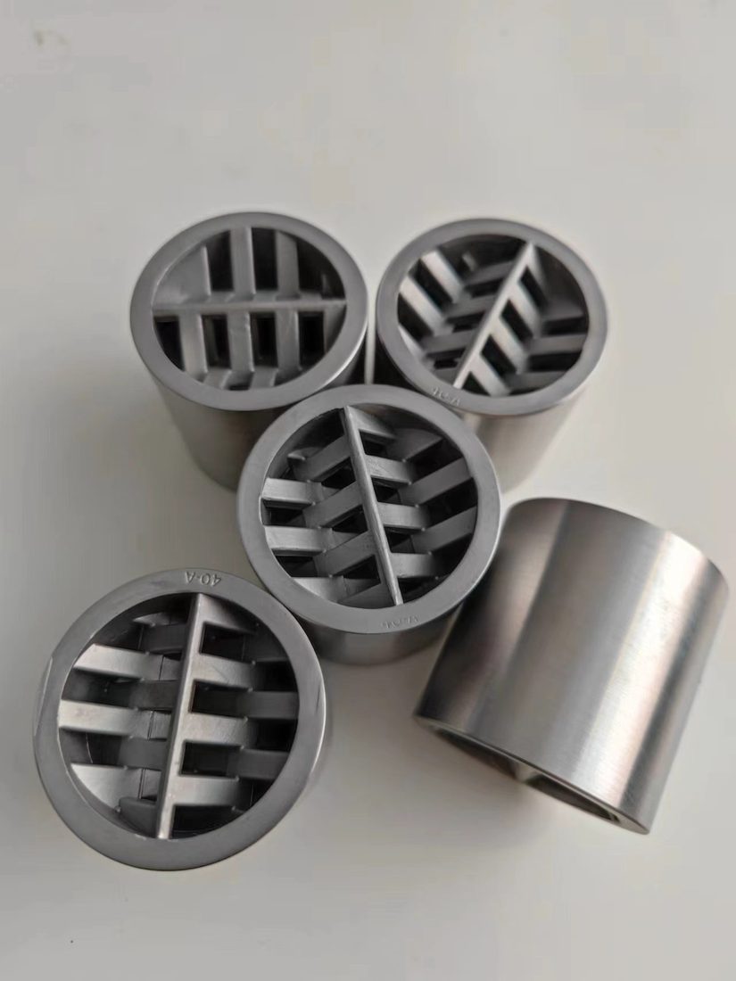
Static mixers are forgiving devices — no motor, no bearings, no shaft alignment — but a handful of geometric rules still decide whether the delivered CoV matches the datasheet. This page condenses them into three tables you can check at installation time, before the line is closed up. For the sizing decisions that come before installation, see the sizing guide.
Table 1 — Allowed Orientation by Mixer Geometry
Because nothing rotates, gravity has no role in the mixing mechanism: mixer manufacturers including Statiflo note that the vertical-vs-horizontal choice is driven by space, headroom, and maintenance access rather than by mixing performance. The exceptions in the table are hydraulic, not mechanical.
| Orientation | SV / SX / SL / SH | SK (incl. gas-liquid) | Notes |
|---|---|---|---|
| Horizontal | Preferred | OK for liquid blending | Easiest access for inspection and removal |
| Vertical upflow | OK | Standard for gas-liquid duty | Bubbles disengage upward instead of pooling in element channels |
| Vertical downflow | OK if line runs full | Avoid for gas-liquid | Dissolved gas can accumulate at the high point and de-wet the elements |
| Any angle (skids) | OK | OK | Keep the line full and respect straight-run lengths |
Sanitary service adds two requirements on horizontal runs: a slight self-draining slope (about 1°) and full-bore isolation valves at both ends — see our sanitary mixer page. On vertical installations, plan a drain port at the lower flange.
Table 2 — Straight-Run Requirements by Pipe Size
Distorted velocity profiles — swirl from elbows, partially closed valves, reducers — degrade mixing quality and raise pressure drop. The conservative specification is 5D upstream / 3D downstream; CFD studies put the working minimum at 3D upstream and 1D downstream, with 1D acceptable downstream when the next component is not a flow meter.
| Pipe size | Upstream 5D | Downstream 3D | Absolute minimum (3D / 1D) |
|---|---|---|---|
| DN25 | 125 mm | 75 mm | 75 / 25 mm |
| DN50 | 250 mm | 150 mm | 150 / 50 mm |
| DN80 | 400 mm | 240 mm | 240 / 80 mm |
| DN100 | 500 mm | 300 mm | 300 / 100 mm |
| DN150 | 750 mm | 450 mm | 450 / 150 mm |
| DN200 | 1,000 mm | 600 mm | 600 / 200 mm |
The Five Most Common Installation Mistakes
Field service literature — including tube-mixer installation guides from Promix and manufacturer IOM manuals such as Westfall's — keeps finding the same five errors:
| Mistake | Consequence | Check before… |
|---|---|---|
| Flow arrow ignored — mixer installed backwards | Directional element designs lose most of their mixing performance | Bolting up: verify the housing arrow against actual flow |
| Element tabs facing the wrong way vs the injection quill | Additive rides along the pipe wall instead of being sheared into the stream; Westfall's manual requires quill tips behind the element leading edges (tabs protrude downstream) | Flanging up downstream of an injection point |
| Straight run skipped "to save space" | Swirled inlet profile degrades CoV and adds pressure drop | Layout approval: measure Table 2 lengths on the isometric |
| No pipe support adjacent to the mixer | Housing and connections carry pipe weight and bending stress | Hydraulic test: supports take the load, not the flanges |
| Low points and non-draining horizontal sanitary runs | Residual hold-up, cleaning failures, CIP dead legs | Sanitary installation: slope ~1°, full-bore valves, drain port |
Pre-Closure Checklist
Before the insulation goes on and the line is closed: flow arrow verified; orientation matches Table 1; straight runs match Table 2; housing flanges centered on the pipe axis with standard gaskets and bolting; adjacent pipe supported; and for sanitary duty, slope and drainage confirmed. Five minutes with this list is cheaper than reopening the line after a failed mixture-quality test.
If your layout cannot meet the straight-run lengths — crowded skids and retrofit ties-ins often cannot — send us the piping isometric and we will check whether a shorter-geometry model or a relocated injection point solves it before you order.
Frequently Asked Questions
Yes — all standard geometries work in horizontal or vertical orientation because there are no rotating parts and gravity does not participate in the mixing mechanism. Vertical upflow is preferred over downflow (dissolved gas accumulates at high points in downflow), and vertical upflow is the standard orientation for gas-liquid duties such as SK-type contacting.
A minimum of 5 pipe diameters (5D) upstream after any elbow, tee, or partially closed valve, and 3D downstream before the next disturbance. CFD studies put the absolute minimum at 3D upstream and 1D downstream, but 5D/3D is the conservative specification. For DN100 that is 500 mm upstream and 300 mm downstream.
Yes. Check the flow arrow on the housing before bolting up: many element designs are directional, and installing the mixer backwards severely reduces mixing performance. Manufacturer installation manuals (for example Westfall's IOM) additionally require the element tabs to face downstream and injection quill tips to sit behind — upstream of — the element leading edges.
Support the adjoining piping so the mixer housing and its flanged or threaded connections do not carry pipe weight or bending stress. For sanitary horizontal runs, fit the housing with a slight slope (about 1 degree) for self-draining, with full-bore isolation valves at both ends and a drain port at the lower flange in vertical installations.